Hello!
Monitoring electricity consumption in the home is pivotal for controlling costs and optimizing consumption. Transitioning from this understanding to practical implementation, one widely recognized solution for measuring energy usage is the Eastron SDM120M single-phase meter. In the following discourse, I will elucidate the seamless integration of this meter into a Home Assistant home automation system, leveraging an affordable ESP board and the open-source ESPHome software.
By integrating this meter, you’ll gain real-time energy consumption monitoring, access detailed metering data, and create custom automations based on meter readings. This integration offers an easy and affordable method to manage your energy usage effectively and reduce your bills.
This comprehensive guide will take you through the entire process, from preparing the hardware to configuring the software and integrating the meter with Home Assistant. It empowers you with complete control over your home’s electricity consumption.
Let’s get started! 🚀
What is ESP32?
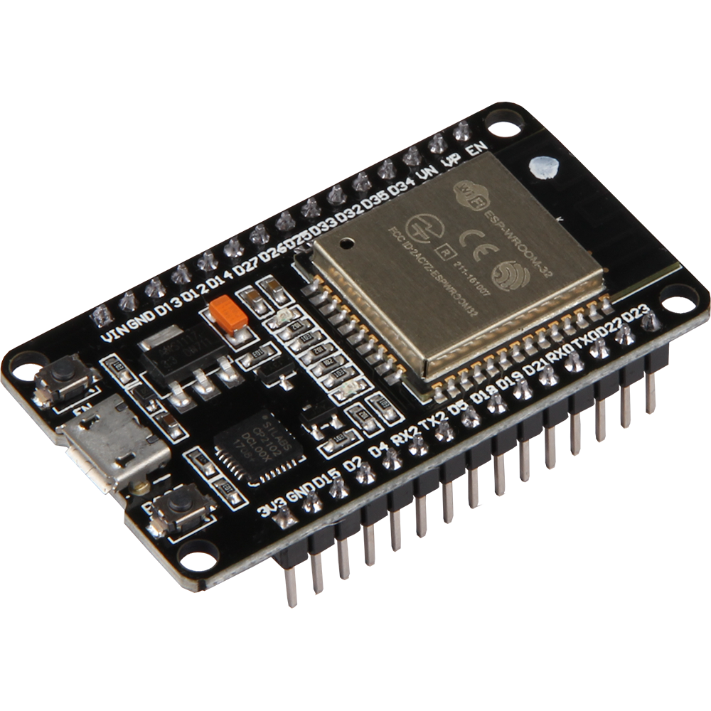
ESP32 is a very popular microcontroller developed by Espressif Systems. It is the successor to the ESP8266 and offers a number of improvements and additional features. The ESP32 is equipped with a dual-core Xtensa LX6 processor that runs at up to 240 MHz, providing enough processing power to handle a variety of tasks.
One of the main advantages of the ESP32 is its versatility and support for various communication interfaces. For instance, it supports WiFi, Bluetooth Classic, and Bluetooth Low Energy (BLE). Consequently, it becomes ideal for IoT (Internet of Things) applications, wireless projects, and other applications requiring wireless communication. Additionally, the ESP32 has built-in peripherals to support interfaces such as SPI, I2C, and UART. Consequently, it’s easy to integrate with various sensors and devices.
Moreover, the microcontroller is popular due to its low price, availability in the market, and extensive development environment. This includes the ESP-IDF platform and support for the Arduino IDE. As a result, it becomes an excellent choice for both beginners and experienced developers looking to create embedded applications and IoT projects.
What is ESPHome?
![]()
ESPHome is a powerful, open source development environment designed specifically for devices based on the popular ESP8266 and ESP32 microcontrollers. Its main goal is to facilitate the creation of smart Internet of Things (IoT) devices, which can then be fully integrated and controlled through the Home Assistant platform.
Configuration of devices in ESPHome is done through friendly files in YAML format, which allow defining the operation of various components, sensors, displays or actuators. This makes programming intuitive and accessible even to those without in-depth coding knowledge.
In addition to native integration with Home Assistant, ESPHome also supports a wide range of off-the-shelf modules and libraries, allowing it to support many popular other components.
Preparation
Before we dive into adapting system using the ESP32/ESP8266 and ESPHome, it’s a good idea to prepare properly. Below you will find the key steps to get your project started.
Make sure you have all the necessary materials:
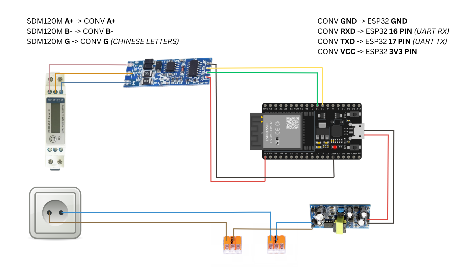
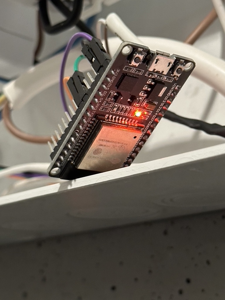
- ESP8266 NodeMCU board (or ESP32, if you opt for a newer model),
- It is worth verifying before purchasing an ESP board that Wi-Fi coverage reaches our installation site. We may need to purchase a board with the ability to connect an external antenna.
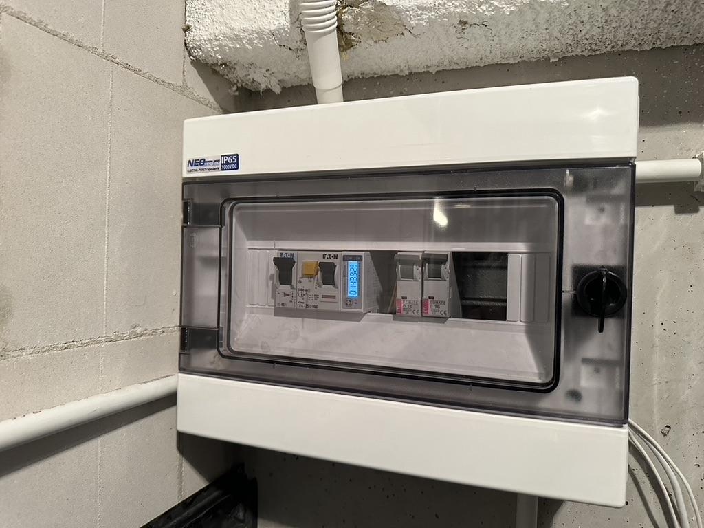
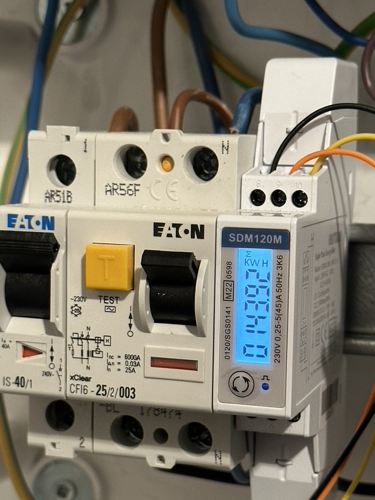
- Eastron SDM120M – Modbus RS485 single-phase electricity meter (Shop link),
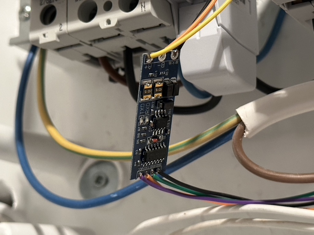
- TTL to RS485 Adapter – Converter Module (Shop Link),
- Power source for the ESP8266 board (5V DC),
- Wire connectors,
- (Optional) DIN box in which to hide the ESP board with the converter module,
- Connection wires for all components.
Installing ESPHome in Home Assistant
Install ESPHome in your Home Assistant environment to easily configure and manage the ESP8266. Use the ESPHome documentation and follow the instructions.
Preparation of workspace
Organize a workspace where you will assemble the system. Make sure you have access to tools and are comfortable working on the project.
Health and safety of working with electric voltage
 Electrical safety is key when working with electricity. Here are some important recommendations:
- Power Off: Before any work on the circuit, turn off the power supply to avoid electric shock.
- Appropriate Tools: Use tools that are insulated and designed for electrical work – they should meet appropriate safety standards.
- Experience: Electrical installation work requires experience. If you are unsure of your skills, it is advisable to enlist the help of an experienced person.
- Eye and Hand Protection: Wearing eye and hand protection is recommended, especially when soldering and handling connections.
- Check the Power Supply: Make sure you know where the main power supply is and that it is off before taking any action.
- Knowledge of the Electrical System: Always verify that you know how an electrical system works. Do not take action blindly.
Step 1 – VLAN IoT
As a security practice, I recommend setting up a separate network for IoT devices, separate from the main home network. For this purpose, it is worth using the VLAN (Virtual Local Area Network) function, which allows physical separation of devices, such as those based on ESPHome, from other devices in the home infrastructure.
Benefits
Creating a dedicated network for IoT devices offers several advantages:
- Security: Separating IoT devices from the main network haelps minimize the potential risk of attacks. If an IoT device is possibly compromised, access to the main home network is difficult.
- Controlling Communications: Creating a separate network allows for more precise control over who communicates with IoT devices and how. You can define communication rules that only allow specific devices (for example, a server or virtual machine from Home Assistant) to interact with IoT devices.
- Network Traffic Optimization: Separating IoT device traffic from main network traffic can help optimize network performance.
Implementation
To implement such separation, it is worth consulting the documentation and settings of the router. In the case of Home Assistant, using the appropriate firewall rules on the router, you can customize access to IoT devices. This approach introduces a layer of additional security to our smart home infrastructure.
Step 2 – Install and configure firmware to work with Home Assistant
Once the ESPHome add-on is running on the Home Assistant server, it’s time to move on to adding the first ESPHome-based device.
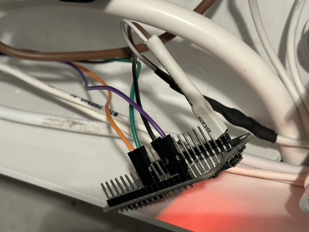
Connecting to a computer
- Connect the board using a USB cable to your computer. It is important to use a USB cable with data transmission, as many cheap cables only provide power.
- To be sure of correct operation, I recommend using Chrome or Edge browser (there is a transfer of data transmission through the COM port to the browser using WebSerial).
Home Assistant
- After completing these steps, log in to Home Assistant,
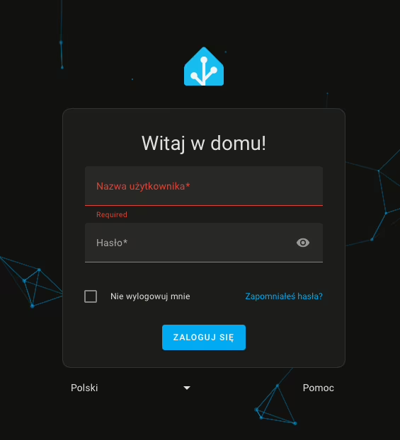
- From the side panel, go to the ESPHome tab,
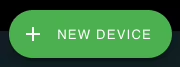
- Then click New Device,
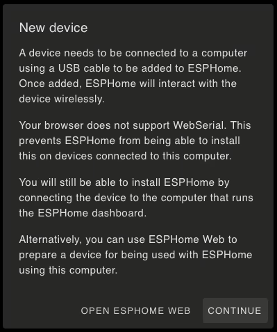
After selecting the option to add a new device, we may encounter a browser incompatibility message, especially for browsers that do not support WebSerial. Alternatively, we may also encounter a message indicating that there is no secure connection (HTTPS) to the dashboard. In this situation, we can click Continue to continue the process of adding the device.
- In the next window, we enter a name for our device (it can be a name or alias we created) and the details of our Wi-Fi network.
- Wi-Fi network entry is only necessary when adding a device for the first time. Subsequent ESPHome-based additions will not require this step.
- Then, for ESPHome to install the firmware on the ESP8266 board, click Connect.
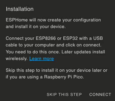
- After a while, the browser will display a window for selecting a device for serial port communication. Find your device, whose name should include CP210x UART, and click Connect.
- Then wait until the firmware is installed on the board.
Completion of the process
After a successful installation, you should receive a message confirming the completion of the process. Your device will also appear on the dashboard with the description ONLINE. This means that the board has been correctly configured and is ready to proceed.
Step 3 – Upload the code in ESPHome

Step 6 – Reverse proxy on Synology using Nginx Proxy Manager
Do you use Synology and want to improve access to your Home Assistant server? Here’s a quick step-by-step guide on how to set up a login using a domain name and subdomain, such as ha.xyz.com, instead of entering an IP address. You can achieve all this with Docker Compose in the Portainer.
👉 Check it out now and get your environment ready for more improvements!
Thus, by using a domain name instead of an IP address, you simplify the process of logging into your Home Assistant server on Synology.
Step 7 – Adding a device to Home Assistant
- In the Home Assistant notification section, you’ll notice that our home automation server has detected a new device,
- Next, navigate to Settings, then to Integrations and Devices,
- You’ll see the new device highlighted with a blue border. Approve the new device for integration.
- Afterward, set the area where the device will be located. In our case, it will be in Storage.
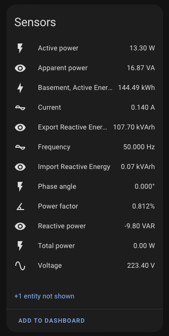
- Congratulations! You’ve reached this stage, indicating a successful configuration process. To verify the performance of your new device, you can directly access it from Home Assistant and check the parameters measured by the electricity meter. 🚀
If you have additional questions about the setup, go ahead and leave a comment under this article or contact me directly. I will be happy to answer any concerns and help solve any problems. Your questions can help improve this guide for other users.
Additional materials and information
For further exploration and more information, I recommend checking out the links below. They are valuable sources that were used in the development of this guide.
- Getting Started with ESPHome and Home Assistant. https://esphome.io/guides/getting_started_hassio#installing-esphome-dashboard
- Eastron SDM Energy Monitor. https://esphome.io/components/sensor/sdm_meter
- SDM120 Series Manual. https://www.eastroneurope.com/images/uploads/products/manuals/SDM120_Series_Manual_.pdf
Read also
Here are some articles related to your interests:
- Home Assistant: BME280 sensor installation via ESPHome. Learn how to create a simple weather station for your balcony using ESPHome and Home Assistant with the BME280 sensor.
- Nginx Proxy & Cloudflare: How to restore a real IP address. Discover how to restore users’ real IP addresses in server logs using Nginx Proxy Manager and Cloudflare as a reverse proxy.
- TVHeadend: SAT>IP decoder installation and configuration. Follow a step-by-step guide to configuring a SAT>IP decoder with TVHeadend in Docker Compose using the Telestar Digibit Twin.
- How to configure a Leox GPON ONT module on a Mikrotik router. Learn how to configure the Leox LXT-010S-H GPON ONT module on a Mikrotik RB5009 router instead of the ONT module from Orange.
- UniFi Network Application: Connecting an Access Point from another network. Discover how to connect a Ubiquiti UniFi device from another network to the Network Application, using Mikrotik’s IPSec tunnel as an example.
- UniFi Controller in Docker: Migrating to UniFi Network Application. Follow a step-by-step guide to successfully migrating to the Network Application using Docker Compose.
- ADS-B: Installing and configuring the receiver on a Raspberry Pi. Learn how to install and configure your own ADS-B antenna on a Raspberry Pi to track aircraft in real-time.
- Traccar: A guide to installing on Synology in Docker. Follow a step-by-step guide to installing Traccar on Synology using Docker for effective vehicle tracking on your own server.
Leave a Reply