Hello!
Smart home solutions are becoming more and more popular, offering convenience, energy savings and better control over our environment. One tool that facilitates the creation of such systems is ESPHome, a powerful platform based on ESP chips. It allows you to program various sensors and devices to gain full control of your smart home.
In today’s tutorial, we will use ESPHome to create a simple but extremely useful weather station for the balcony. We will use the BME280 sensor to measure temperature, humidity and atmospheric pressure. This will allow you to monitor weather conditions in the immediate area in real time.
Creating a weather station using ESPHome is not only practical, but also a great opportunity to learn the basics of programming home automation systems. We will take you step by step through the entire process – from setting up the environment, to connecting the sensor, to visualizing the data on a sample interface.
Ready? Fasten your seat belts, because it’s time to bring some intelligence into your home! Let’s start the adventure with ESPHome and the weather station on the balcony. 🚀
What is the ESP8266 NodeMCU?
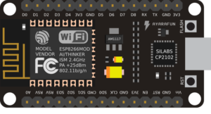 The ESP8266 NodeMCU is a small but extremely powerful development board based on the popular ESP8266 chip from Espressif. Equipped with an integrated Wi-Fi module operating at 802.11 b/g/n, it allows easy connection to existing wireless networks and communication with other devices over the Internet.
At the heart of the board is a 32-bit Tensilica L106 processor at 80-160 MHz and 64 KiB of instruction memory and 96 KiB of data memory. The NodeMCU has a built-in USB-UART converter (CP2102), so it can be easily connected to a computer and programmed using the Arduino IDE or other environment.
A key advantage is the existence of as many as 17 GPIO (General-Purpose Input/Output) pins, which can be freely used as digital I/O or assigned other functions, such as I2C, SPI, UART, etc. This allows communication and control of all kinds of sensors, displays and executive devices.
Despite its compact size and low price, the ESP8266 NodeMCU has great potential in DIY and Internet of Things projects thanks to its strong capabilities, low cost and excellent community support.
What is ESPHome?
![]()
ESPHome is a powerful, open source development environment designed specifically for devices based on the popular ESP8266 and ESP32 microcontrollers. Its main goal is to facilitate the creation of smart Internet of Things (IoT) devices, which can then be fully integrated and controlled through the Home Assistant platform.
Configuration of devices in ESPHome is done through friendly files in YAML format, which allow defining the operation of various components, sensors, displays or actuators. This makes programming intuitive and accessible even to those without in-depth coding knowledge.
In addition to native integration with Home Assistant, ESPHome also supports a wide range of off-the-shelf modules and libraries, allowing it to support many popular other components.
Preparation
Before we dive into adapting the remote control to our system using the ESP8266 and ESPHome, it’s a good idea to prepare properly. Below you will find the key steps to get your project started:
Make sure you have all the necessary materials:
- ESP8266 NodeMCU board (or ESP32, if you opt for a newer model),
- It is worth verifying before purchasing an ESP board that Wi-Fi coverage reaches our installation site. We may need to purchase a board with the ability to connect an external antenna.
- Waveshare BME280 temperature, pressure and humidity sensor (Shop link),
- Power source for the ESP8266 board (5V DC),
- Wire connectors,
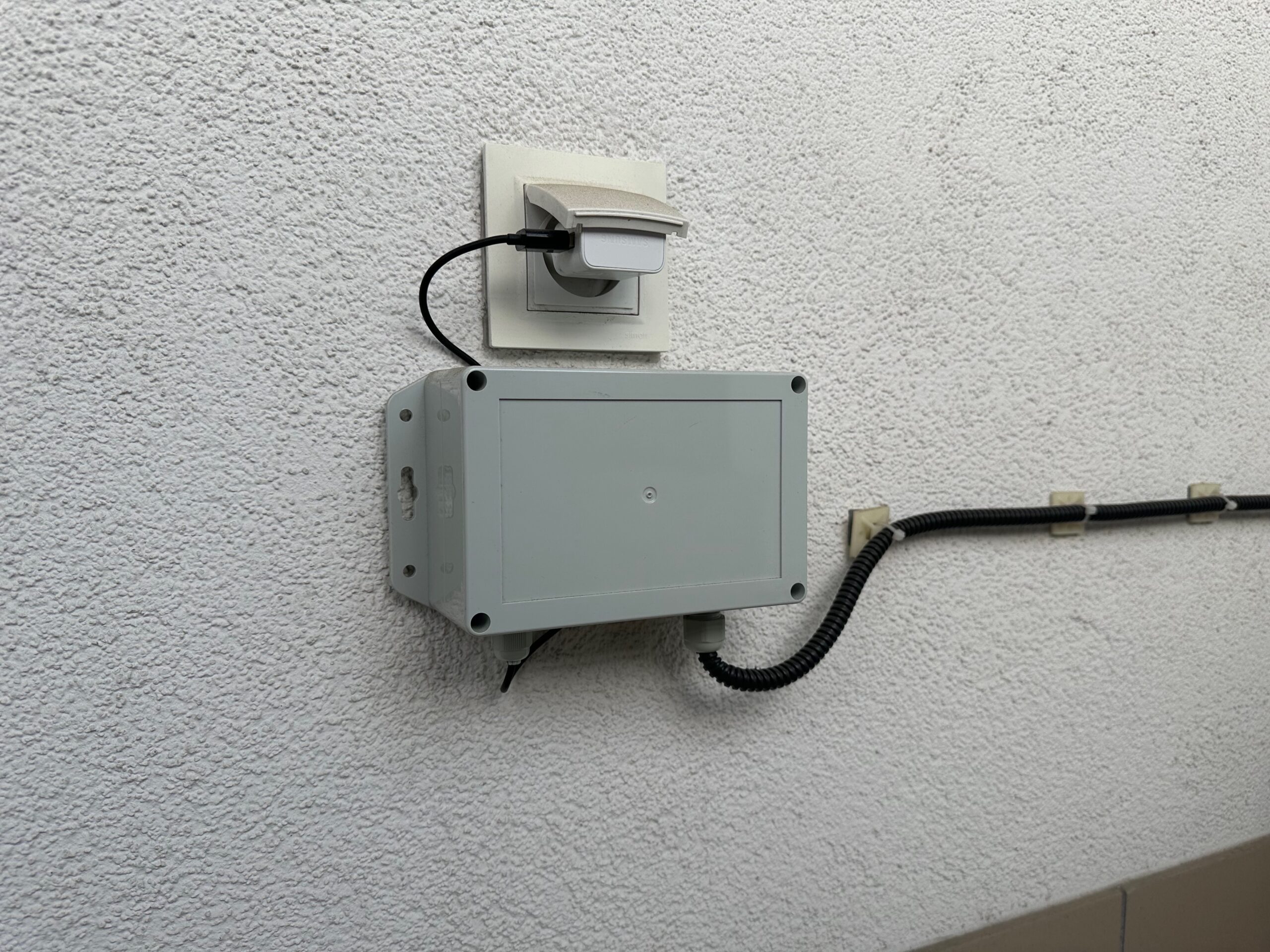
- A box in which to hide the plate (weatherproof),
- Meteorological Cage,
- Connection wires for all components.
Installing ESPHome in Home Assistant
Install ESPHome in your Home Assistant environment to easily configure and manage the ESP8266. Use the ESPHome documentation and follow the instructions.
Preparation of workspace
Organize a workspace where you will assemble the system. Make sure you have access to tools and are comfortable working on the project.
Step 1 – VLAN IoT
As a security practice, I recommend setting up a separate network for IoT devices, separate from the main home network. For this purpose, it is worth using the VLAN (Virtual Local Area Network) function, which allows physical separation of devices, such as those based on ESPHome, from other devices in the home infrastructure.
Benefits
Creating a dedicated network for IoT devices offers several advantages:
- Security: Separating IoT devices from the main network haelps minimize the potential risk of attacks. If an IoT device is possibly compromised, access to the main home network is difficult.
- Controlling Communications: Creating a separate network allows for more precise control over who communicates with IoT devices and how. You can define communication rules that only allow specific devices (for example, a server or virtual machine from Home Assistant) to interact with IoT devices.
- Network Traffic Optimization: Separating IoT device traffic from main network traffic can help optimize network performance.
Implementation
To implement such separation, it is worth consulting the documentation and settings of the router. In the case of Home Assistant, using the appropriate firewall rules on the router, you can customize access to IoT devices. This approach introduces a layer of additional security to our smart home infrastructure.
Step 2 – Install and configure firmware to work with Home Assistant
Once the ESPHome add-on is running on the Home Assistant server, it’s time to move on to adding the first ESPHome-based device.
Connecting to a computer
- Connect the board using a USB cable to your computer. It is important to use a USB cable with data transmission, as many cheap cables only provide power.
- To be sure of correct operation, I recommend using Chrome or Edge browser (there is a transfer of data transmission through the COM port to the browser using WebSerial).
Home Assistant
- After completing these steps, log in to Home Assistant,
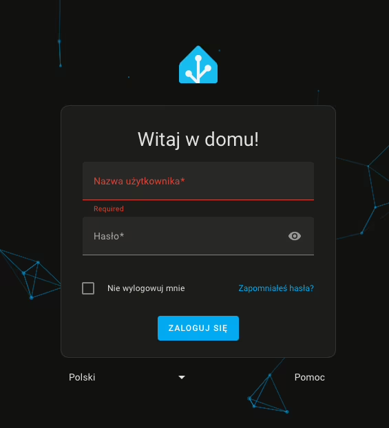
- From the side panel, go to the ESPHome tab,
- Then click New Device,
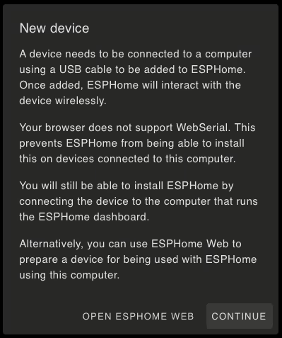
After selecting the option to add a new device, we may encounter a browser incompatibility message, especially for browsers that do not support WebSerial. Alternatively, we may also encounter a message indicating that there is no secure connection (HTTPS) to the dashboard. In this situation, we can click Continue to continue the process of adding the device.
- In the next window, we enter a name for our device (it can be a name or alias we created) and the details of our Wi-Fi network.
- Wi-Fi network entry is only necessary when adding a device for the first time. Subsequent ESPHome-based additions will not require this step.
- Then, for ESPHome to install the firmware on the ESP8266 board, click Connect.
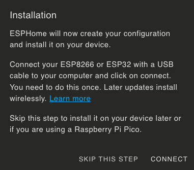
- After a while, the browser will display a window for selecting a device for serial port communication. Find your device, whose name should include CP210x UART, and click Connect.
- Then wait until the firmware is installed on the board.
Completion of the process
After a successful installation, you should receive a message confirming the completion of the process. Your device will also appear on the dashboard with the description ONLINE. This means that the board has been correctly configured and is ready to proceed.
Step 3 – Upload the code in ESPHome
Remember to perform these activities with the highest standards of electrical safety. Make sure all connections are properly secured.
Installation
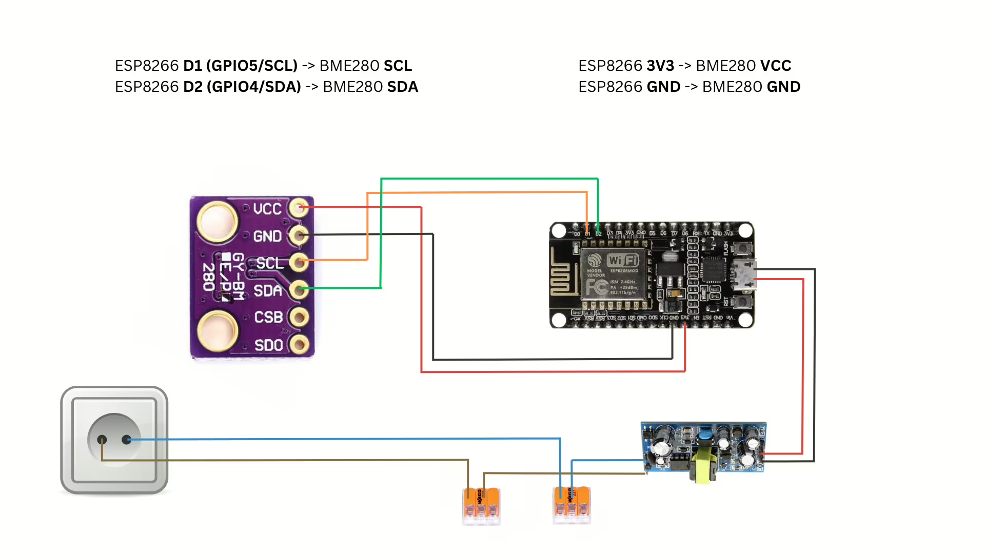
Let’s start by connecting the BME280 sensor to the ESP8266 board. The BME280 communicates via the I2C interface, so we need to connect the appropriate pins:
- Pin D1 (GPIO5) on ESP8266 to SCL line (serial clock)
- Pin D2 (GPIO4) on the ESP8266 is the SDA (Serial Data) line.
Connect as follows:
- SCL pin of BME280 sensor with D1 (GPIO5) pin on ESP8266
- SDA pin of BME280 sensor with D2 (GPIO4) pin on ESP8266
- Connect the ground (GND) of the sensor and ESP8266
- Connect the power supply (VCC) of the sensor to 3.3V on the ESP8266
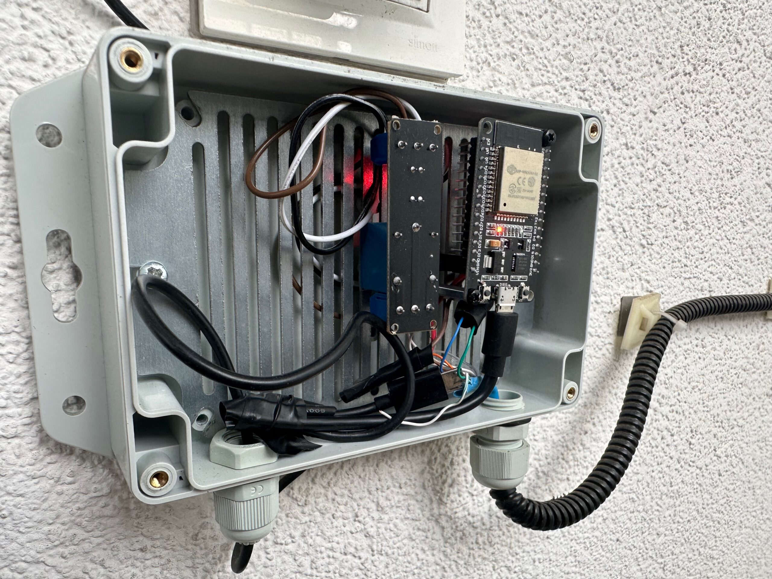
Final verification
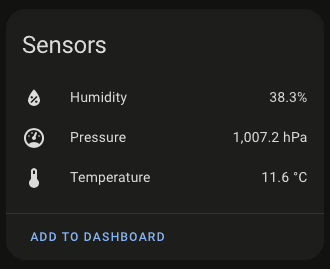
After setting up ESPHome and connecting the BME280 sensor, it’s time to verify the operation of our weather station. Connect the ESP8266 board to the power supply and wait for startup. ESPHome logs should show messages indicating that the BME280 sensor has been detected and readings of temperature, humidity and atmospheric pressure.
You can now test the station’s performance by observing changes in weather parameters or displaying them on an interface of your choice, such as through a web browser or a mobile app that works with Home Assistant.
Many more possibilities
 It is worth mentioning that the same ESP8266 board we used to create the weather station can also be used for other smart home applications. One of them is the control of the estate barrier.
Imagine being able to open and close the barrier using a smartphone or voice assistant – not only a convenience, but also additional security. Using ESPHome and the relay module, you can easily integrate the barrier into your home automation system.
If you are interested in this topic, I recommend you to read my tutorial on installing and configuring remote control of an estate barrier using ESP8266 and ESPHome. There you will find all the necessary step-by-step information.
Step 5 – Reverse proxy on Synology using Nginx Proxy Manager
Do you use Synology and want to improve access to your Home Assistant server? Here’s a quick step-by-step guide on how to set up a login using a domain name and subdomain, such as ha.xyz.com, instead of entering an IP address. You can achieve all this with Docker Compose in the Portainer.
👉 Check it out now and get your environment ready for more improvements!
Thus, by using a domain name instead of an IP address, you simplify the process of logging into your Home Assistant server on Synology
Step 6 – Adding a device to Home Assistant
- In the Home Assistant notification section, you should see that our home automation server has detected a new device,
- Go to Settings, then to Integrations and Devices.
- The new device will bear a blue border. We approve the new device for integration.
- Set the area where the device will be located. In our case, it will be the Loggia.
- Congratulations! You have reached this stage, which means that you have successfully gone through the configuration process. To check the operation of your new device, you can directly go to it and control the sensor parameters from the Home Assistant. 🚀
If you have additional questions about the setup, go ahead and leave a comment under this article or contact me directly. I will be happy to answer any concerns and help solve any problems. Your questions can help improve this guide for other users.
Additional materials and information
For further exploration and more information, I recommend checking out the links below. They are valuable sources that were used in the development of this guide.
- Getting Started with ESPHome and Home Assistant: https://esphome.io/guides/getting_started_hassio#installing-esphome-dashboard
Read also
- Nginx Proxy & Cloudflare: How to restore a real IP address. Discover how to restore users’ real IP addresses in server logs using Nginx Proxy Manager and Cloudflare as reverse proxy.
- TVHeadend: SAT>IP decoder installation and configuration. Telestar Digibit Twin: Discover the step-by-step configuration of a SAT>IP decoder with TVHeadend in Docker Compose in blog post.
- How to configure a Leox GPON ONT module on a Mikrotik router. Step-by-step guide on how to configure Leox LXT-010S-H GPON ONT module on Mikrotik RB5009 router, instead of ONT module from Orange.
- UniFi Network Application: Connecting an Access Point from another network. Discover how to connect a device from Ubiquiti UniFi from another network to Network Application – using Mikrotik’s IPSec tunnel as an example.
- UniFi Controller in Docker: Migrating to UniFi Network Application. UniFi Controller: Discover step-by-step how to successfully migrate to Network Application using Docker Compose.
- ADS-B: Installing and configuring the receiver on a Raspberry Pi. Discover the secrets of installing and configuring your own ADS-B antenna on a Raspberry Pi. Develop skills and track aircraft in real time.
- Traccar: A guide to installing on Synology in Docker. Step-by-step guide: Installing Traccar on Synology using Docker. Effective vehicle tracking on your own server.
Comments (1)
Nexsays:
28/09/2024 at 11:29Thanks for the write-up. Had to troubleshoot to get it working. Issues were in the YAML code, I had to swap it to SDA: 4 and SCL: 5 (line 34-35) and had to use address: 0x76 (line 52). Had originally thought the seller sold me a BMP280 instead, which would have made me change the code to bmp280_i2c (line 44) and removal of humidity sensor code (line 50-51).