Press ESC to close

Home Assistant: Remote water meter reading via ESPHome

Table of contents

Hello!

In the era of the smart home, remote reading of utility consumption is becoming more and more popular, and integrating this data with home automation systems such as Home Assistant allows for better asset management and cost optimization. In this article, I’ll show you how to set up remote reading of an Apator water meter using an inexpensive ESP32 board and open-source ESPHome software.

This will allow you to easily monitor your water consumption without having to manually read the meter. I will guide you through the installation, configuration and integration process to enjoy full automation in your smart home.

Let’s get started! 🚀

What is ESP32?

NodeMCU ESP32 | Joy-IT

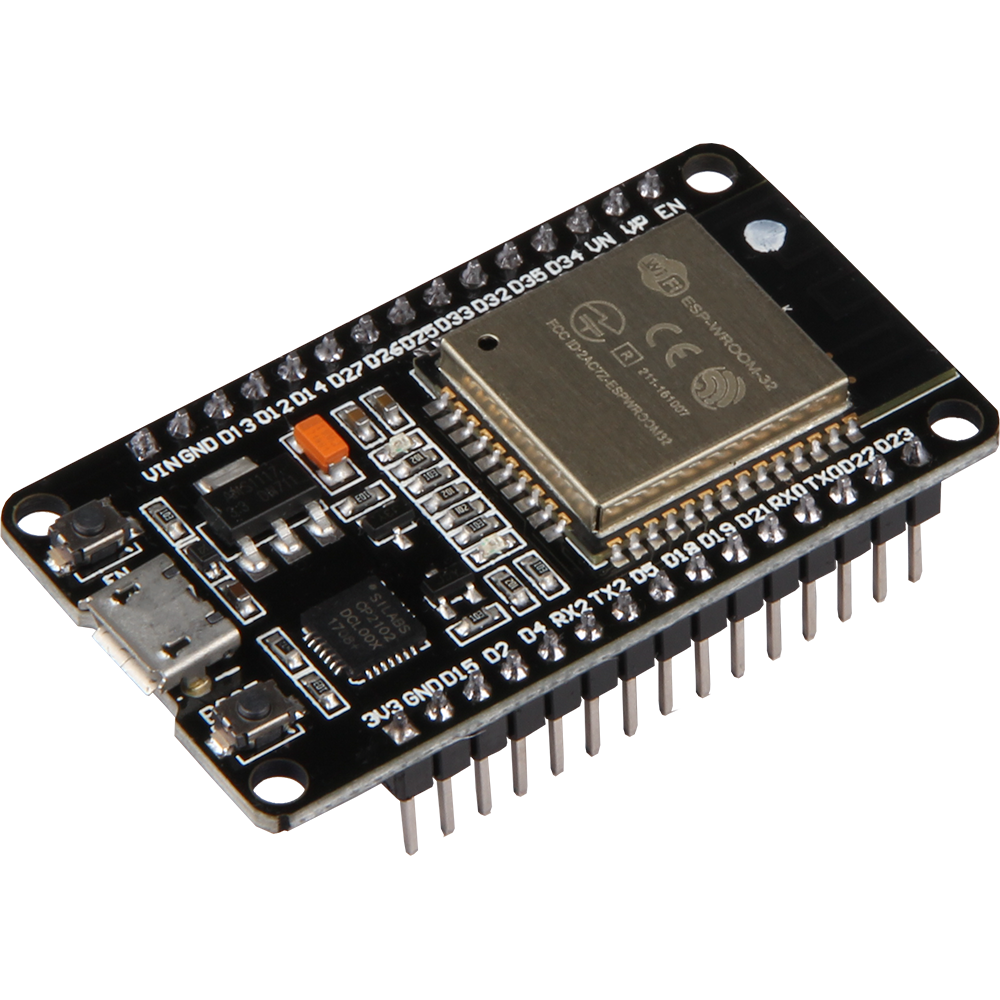
ESP32 is a very popular microcontroller developed by Espressif Systems. It is the successor to the ESP8266 and offers a number of improvements and additional features. The ESP32 is equipped with a dual-core Xtensa LX6 processor that runs at up to 240 MHz, providing enough processing power to handle a variety of tasks.

One of the main advantages of the ESP32 is its versatility and support for various communication interfaces, such as WiFi, Bluetooth Classic and Bluetooth Low Energy (BLE). This makes it ideal for IoT (Internet of Things) applications, wireless projects and other applications requiring wireless communication. In addition, the ESP32 has built-in peripherals to support interfaces such as SPI, I2C, UART, making it easy to integrate with various sensors and devices.

The microcontroller is also popular due to its low price, availability in the market, and extensive development environment, which includes the ESP-IDF platform and support for the Arduino IDE. This makes it an excellent choice for both beginners and experienced developers looking to create embedded applications and IoT projects.

What is ESPHome?

ESPHome, New logo

ESPHome is a powerful, open source development environment designed specifically for devices based on the popular ESP8266 and ESP32 microcontrollers. Its main goal is to facilitate the creation of smart Internet of Things (IoT) devices, which can then be fully integrated and controlled through the Home Assistant platform.

Configuration of devices in ESPHome is done through friendly files in YAML format, which allow defining the operation of various components, sensors, displays or actuators. This makes programming intuitive and accessible even to those without in-depth coding knowledge.

In addition to native integration with Home Assistant, ESPHome also supports a wide range of off-the-shelf modules and libraries, allowing it to support many popular other components.

Preparation

Before diving into system adaptation using ESP32/ESP8266 and ESPHome, it’s a good idea to prepare properly. Below are the key steps to start the project.

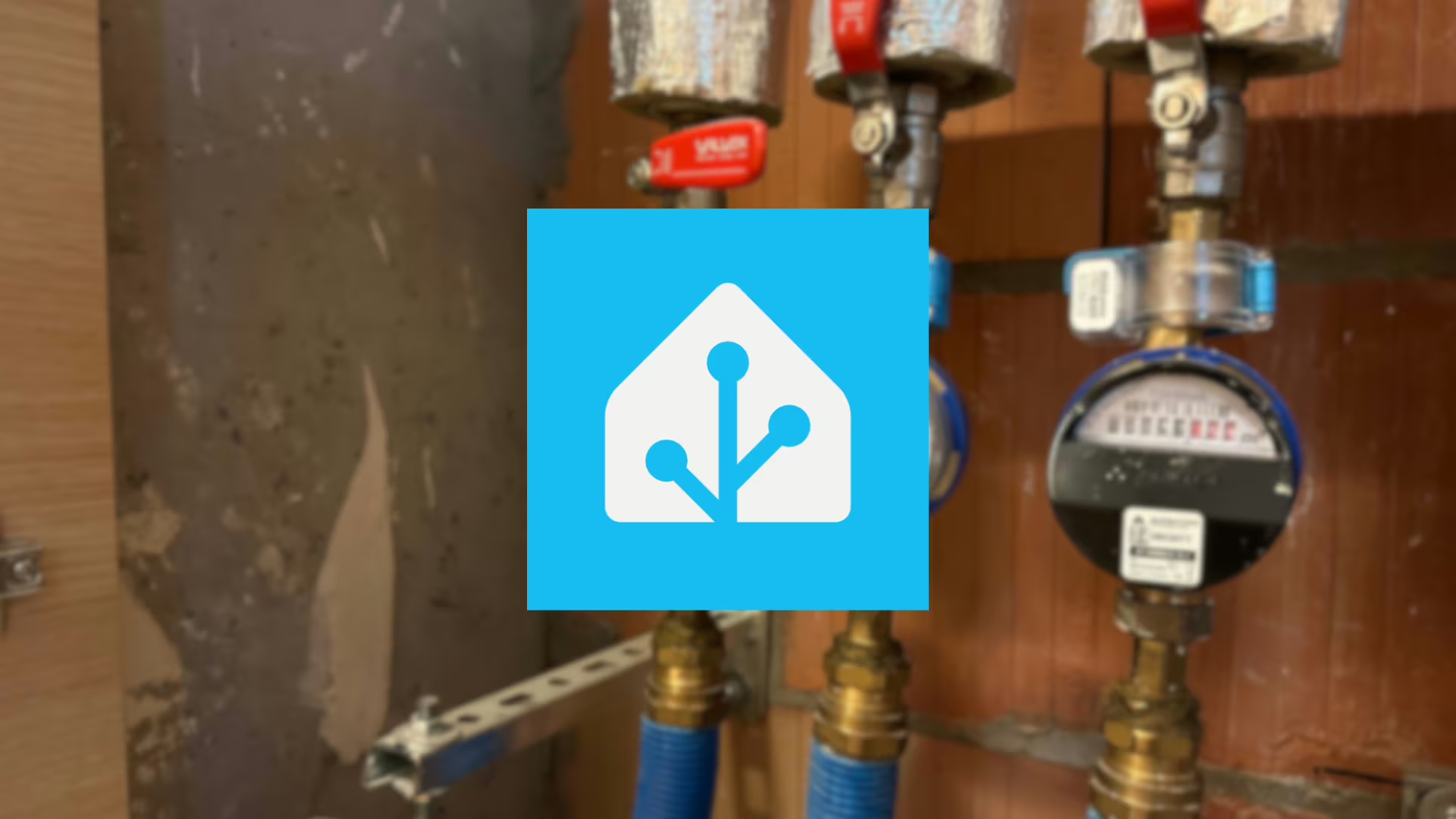
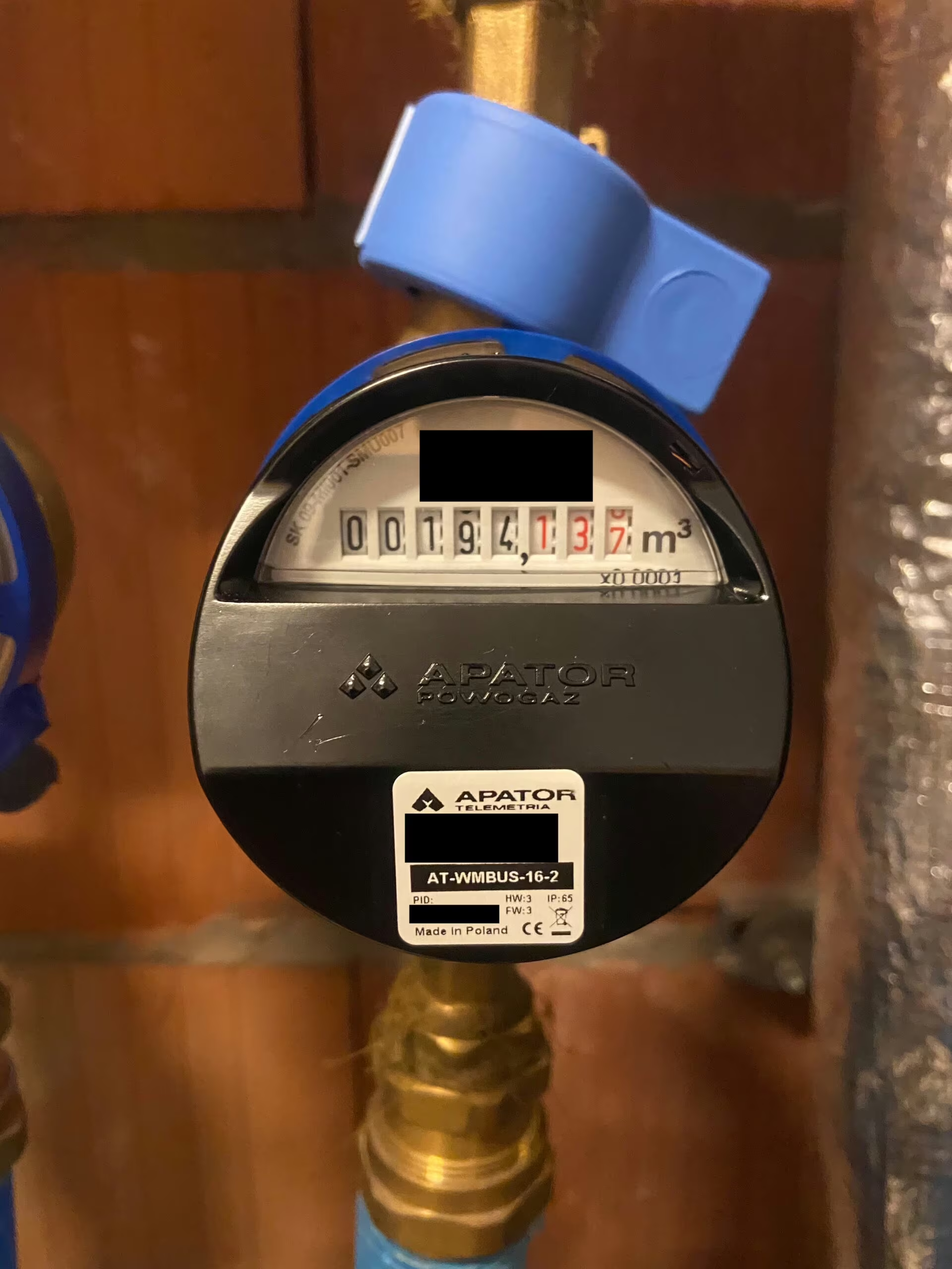
In this article we will focus on the integration of the Apator JS Smart C+ water meter, which is a single-jet water meter of Polish manufacture. This water meter has been adapted for installation of different types of overlays, including radio overlay for Wireless M-Bus, pulse and M-Bus communication. In our case, we will use the Apator AT-WMBUS-16-2 overlay, which will enable us to remotely read the water meter readings using Wireless M-Bus technology and integrate with ESPHome system.

Make sure you have all the necessary materials:

  • ESP8266 NodeMCU board (or ESP32, if you opt for a newer model),
    • It is worth verifying before purchasing an ESP board that Wi-Fi coverage reaches our installation site. We may need to purchase a board with the ability to connect an external antenna.
  • Apator JS Smart C+ water meter (Link to manufacturer),
  • Apator AT-WMBUS-16 radio readout overlay (Link to manufacturer),
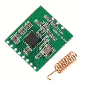
  • CC1101 868 MHz module (Shop link),
  • 868 MHz antenna,
  • Power source for the ESP8266 board (5V DC),
  • Wire connectors,
  • (Optional) DIN box in which to hide the ESP board with the converter module,
  • Connection wires for all components.

Installing ESPHome in Home Assistant

Install ESPHome in your Home Assistant environment to easily configure and manage the ESP8266. Use the ESPHome documentation and follow the instructions.

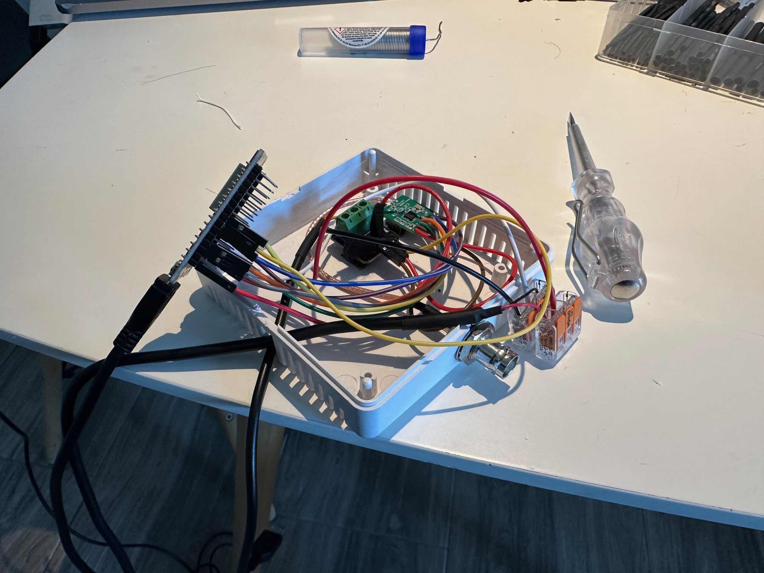
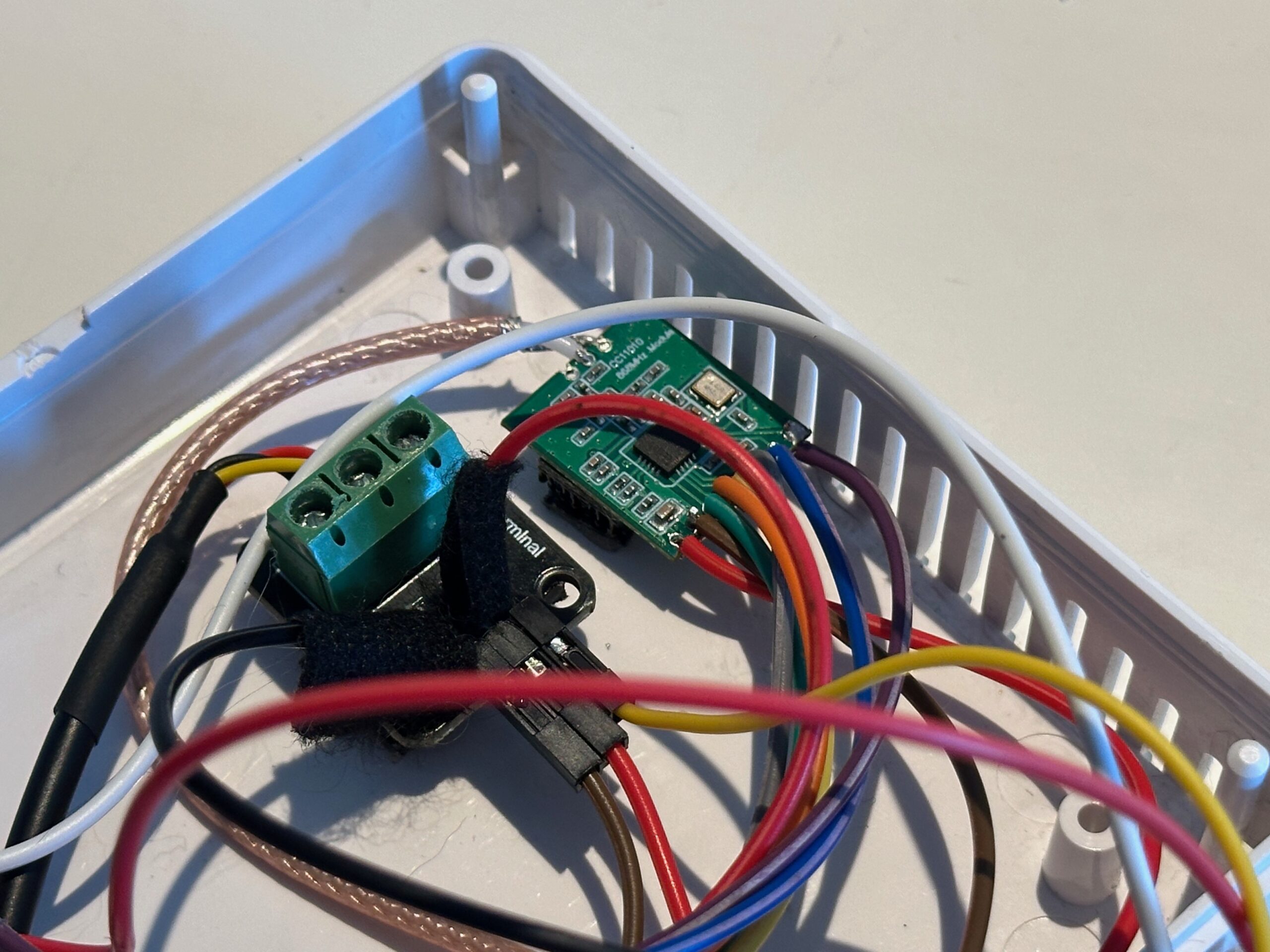
Preparation of workspace

Organize a workspace where you will assemble the system. Make sure you have access to tools and are comfortable working on the project.

Step 1 – VLAN IoT

As a security practice, I recommend setting up a separate network for IoT devices, separate from the main home network. For this purpose, it is worth using the VLAN (Virtual Local Area Network) function, which allows physical separation of devices, such as those based on ESPHome, from other devices in the home infrastructure.

Benefits

Cloud icon as VLAN

Creating a dedicated network for IoT devices offers several advantages:

  • Security: Separating IoT devices from the main network haelps minimize the potential risk of attacks. If an IoT device is possibly compromised, access to the main home network is difficult.
  • Controlling Communications: Creating a separate network allows for more precise control over who communicates with IoT devices and how. You can define communication rules that only allow specific devices (for example, a server or virtual machine from Home Assistant) to interact with IoT devices.
  • Network Traffic Optimization: Separating IoT device traffic from main network traffic can help optimize network performance.

Implementation

To implement such separation, it is worth consulting the documentation and settings of the router. In the case of Home Assistant, using the appropriate firewall rules on the router, you can customize access to IoT devices. This approach introduces a layer of additional security to our smart home infrastructure.

Step 2 – Install and configure firmware to work with Home Assistant

Once the ESPHome add-on is running on the Home Assistant server, it’s time to move on to adding the first ESPHome-based device.

Connecting to a computer

  • Connect the board using a USB cable to your computer. It is important to use a USB cable with data transmission, as many cheap cables only provide power.
    • To be sure of correct operation, I recommend using Chrome or Edge browser (there is a transfer of data transmission through the COM port to the browser using WebSerial).

Home Assistant

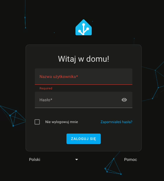
  • After completing these steps, log in to Home Assistant,

Home Assistant, login screen

  • From the side panel, go to the ESPHome tab,
  • Then click New Device,

ESPHome, Button New device

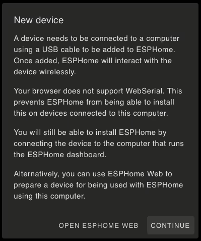
  • After selecting the option to add a new device, we may encounter a browser incompatibility message, especially for browsers that do not support WebSerial. Alternatively, we may also encounter a message indicating that there is no secure connection (HTTPS) to the dashboard. In this situation, we can click Continue to continue the process of adding the device.

ESPHome, New device

  • In the next window, we enter a name for our device (it can be a name or alias we created) and the details of our Wi-Fi network.
    • Wi-Fi network entry is only necessary when adding a device for the first time. Subsequent ESPHome-based additions will not require this step.
  • Then, for ESPHome to install the firmware on the ESP8266 board, click Connect.

ESPHome, Installation

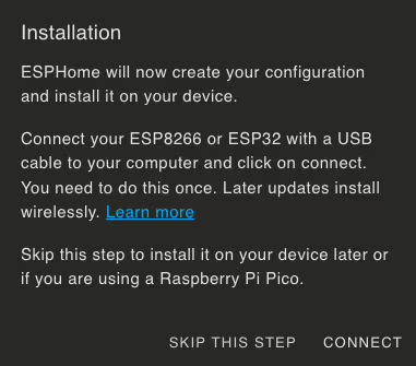
  • After a while, the browser will display a window for selecting a device for serial port communication. Find your device, whose name should include CP210x UART, and click Connect.
  • Then wait until the firmware is installed on the board.

Completion of the process

After a successful installation, you should receive a message confirming the completion of the process. Your device will also appear on the dashboard with the description ONLINE. This means that the board has been correctly configured and is ready to proceed.

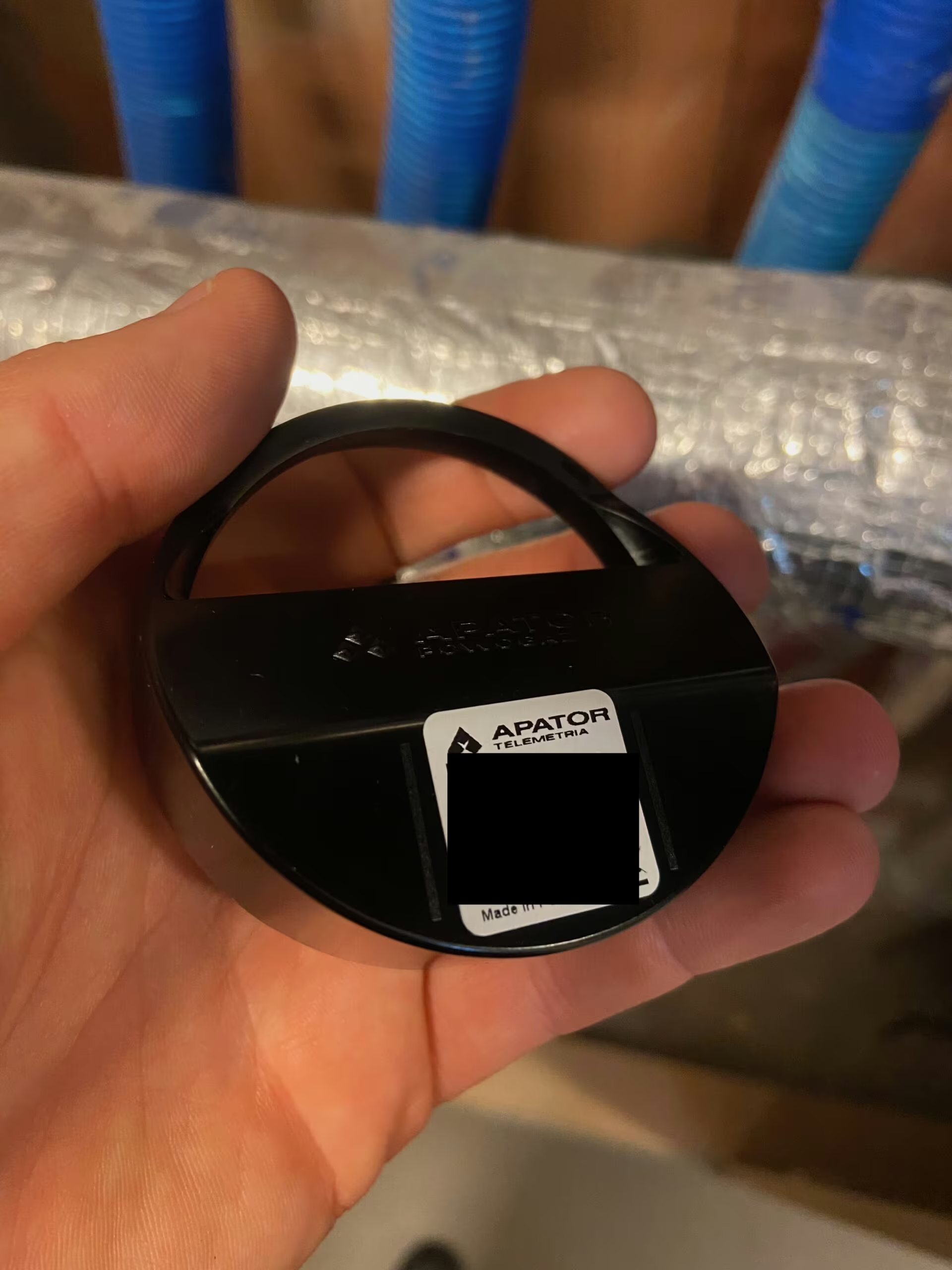
Step 3 – Install the water meter extension cap

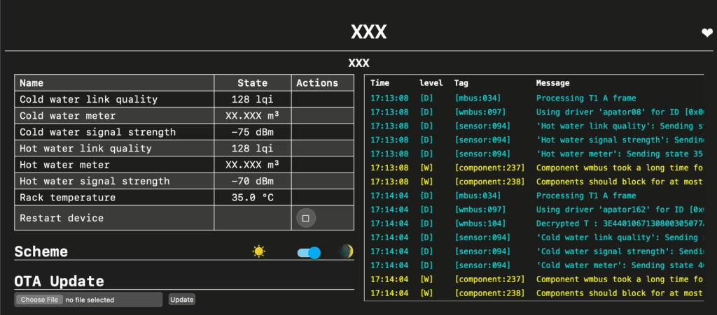
Installing the JS Smart C+ water meter extension cap is super easy. Just put it on the front of the water meter, making sure it fits properly. Before installation, it is worth noting the serial number on the overlay (for models from Apator). This number is crucial, because we will need it for configuration in ESPHome – it is thanks to it that the system will know from which water meter it should read data.

If the extension cap is new, it should be reset to zero, which means there is no stored history of water consumption. To start its operation, it must be awakened with a magnet. In the case of a used extension, it will have a recorded mileage in cubic meters. In this case, awakening with a magnet is not necessary. It is also worth remembering that used overlays may have altered data transmission times – reports may be sent more or less frequently than the manufacturer’s default settings.

In the next steps of the article, I will show how to correct these values so that the display in Home Assistant is consistent with actual water consumption.

Encryption key

If you buy a new extension, you can ask the manufacturer not to set the encryption key. Without the key, you won’t be able to read the transmitted values, so the lack of encryption will make it easier to integrate into the system.

If you purchase a used extension, make sure that the seller has provided you with a decoded extension or provided you with an encryption key. If the encryption key is not available, reading data from the water meter will be impossible.

Security

The encryption key protects the data transmitted between the water meter and the receiver. Encryption ensures that readings are protected from unauthorized reading and tampering. In this way, it is possible to prevent eavesdropping and falsification of data, which is particularly important in the context of water consumption monitoring, where data accuracy is crucial for managing resources and controlling costs.

However, the security related to the encryption key may introduce some difficulties, especially in the context of integration with the ESPHome system. Without the right key, even if the overlay works properly, you won’t be able to read the transmitted data. In this case, you will need to obtain a key from the manufacturer or vendor, which may be an additional step in the setup process.

If the encryption key is not set, the system can operate in “open” mode, which greatly simplifies integration, but also reduces the level of security. So it’s worth finding a balance between security and convenience – if data security is not a priority in your application, the lack of encryption can simplify the whole process.

Step 4 – Connect the radio module to the board

To enable remote reading of data from the water meter, it is necessary to connect the CC1101 radio module operating at 868 MHz to the ESP32 board. You will need a soldering iron for this, as the wires must be soldered to the module and the ESP32 board.

Included with the radio module you will find a short antenna with a frequency of 868 MHz, which you can use. In my installation, however, I decided to use a BNC connector so that I can connect an external antenna, which can improve the signal range.

After soldering the wires, connect them to the appropriate pins on the ESP32 board. If you prefer a different connection arrangement, no problem – just specify the appropriate pins in the code configuration, which I will present later in the article.

Connect the wires according to the following pins:

  • MOSI: GPIO32
  • CLK: GPIO33
  • MISO: GPIO19
  • GDO2: GPIO21
  • GDO0: GPIO22
  • CS: GPIO23

In my configuration, the radio module and ESP32 are located in the teletechnical cabinet. Therefore, I also decided to connect a DS18B20 temperature sensor to the same board, which allows me to monitor the temperature in the rack cabinet using the same device.

Moduł CC1101 868 MHz

The description of the connection pins is described on the back of the CC1101 board.

Step 5 – Upload the code in ESPHome

In this section, we will now upload the relevant entries for the configuration of the connection with the reception of readings from the water meter. Copy the necessary code elements into your installation. We will use an ESPHome-adapted component, developed by a GitHub user named SzczepanLeon. This component can be found in the esphome-components repository.

What is the responsibility?

A custom component based on “wmbusmeters” adds support for the CC1101 module in the Wireless M-Bus standard, which is crucial for communication with the Apator water meter. It makes it possible to read the data frames sent by the radio overlay to the water meter, decode the data, and then send it to Home Assistant via ESPHome.

In the repository you will find detailed instructions on how to configure and upload this component. After completing this step, you will have a fully working remote water meter reading system
esphome:
  name: "esp02-watermeter"
  comment: "Water"
  area: "Office"  

esp32:
  board: esp32dev
  framework:
    type: arduino

web_server:
  port: 80
  local: true  

# Enable Home Assistant API
api:
  encryption:
    key: "HERE WILL BE THE CODE GENERATED BY ESPHOME"

ota:
  - platform: esphome
    password: "HERE WILL APPEAR THE PASSWORD GENERATED BY ESPHOME"

wifi:
  ssid: !secret wifi_ssid
  password: !secret wifi_password  

  # Enable fallback hotspot (captive portal) in case wifi connection fails
  ap:
    ssid: "esp02-watermeter Fallback Hotspot"
    password: "123456789"

captive_portal:

button:
  - platform: restart
    name: "Restart device"

sensor:
  - platform: wmbus
    meter_id: "0xXXXXXXXX"
    add_prefix: false
    type: apator162
    key: "00000000000000000000000000000000"
    lqi:
     name: "Cold water link quality"
     id: "cold_water_meter_lqi"
     unit_of_measurement: "lqi"
     state_class: "measurement"
    rssi:
     name: "Cold water signal strength"
     id: "cold_water_meter_rssi"
     unit_of_measurement: "dBm"
     entity_category: "diagnostic"
    total_water_m3:
     name: "Cold water meter"
     id: "cold_water_meter_m3"
     unit_of_measurement: "m³"
     state_class: total_increasing
     device_class: "water"
     accuracy_decimals: 3
     icon: "mdi:counter"
     filters:
      - offset: -XX.XX
  - platform: wmbus
    meter_id: "0xXXXXXXXX"
    add_prefix: false
    type: apator08
    lqi:
     name: "Hot water link quality"
     id: "hot_water_meter_lqi"
     unit_of_measurement: "lqi"
     state_class: "measurement"
    rssi:
     name: "Hot water signal strength"
     id: "hot_water_meter_rssi"
     unit_of_measurement: "dBm"
     entity_category: "diagnostic"
    total_water_m3:
     name: "Hot water meter"
     id: "hot_water_meter_m3"
     unit_of_measurement: "m³"
     state_class: total_increasing
     device_class: "water"
     accuracy_decimals: 3
     icon: "mdi:counter"   
     filters:
        - offset: -XXX.XXX

time:
  - platform: sntp
    id: time_sntp

external_components:
  - source: github://SzczepanLeon/esphome-components@main
    components: [ wmbus ]

wmbus:
  mosi_pin: GPIO32
  clk_pin: GPIO33
  miso_pin: GPIO19
  gdo2_pin: GPIO21
  gdo0_pin: GPIO22
  cs_pin: GPIO23

  log_unknown: "true"  

In the ESPHome configuration code that I pasted into the article, we define how the ESP32 will communicate with the water meter via the CC1101 module. Here’s what each configuration item means:

Sensor – detailed description
  • platform: wmbus: Specifies that we use the Wireless M-Bus platform to communicate with the water meter.
  • meter_id: "0xXXXXXXXX": This is the unique identifier (ID) of the water meter that allows ESPHome to identify which device it is communicating with. This number should match the serial number of the overlay mounted on the water meter.
  • add_prefix: false: This setting decides whether to add prefixes to entity names. In this case, prefixes are not added, which means that entity names will be simple and without additional designations.
  • type: apator162: Specifies the overlay model for the water meter we are using. The list of types is described in the repository on GitHub.
  • key: "00000000000000000000000000000000": This is the encryption key that is used to decode the data transmitted by the radio overlay. For default settings, use the value “00000000000000000000000000000000”.
Definition of individual sensors

lqi:

  • name: "Cold water link quality": Name of the entity that will represent the quality of the connection to the water meter.
  • id: "cold_water_meter_lqi": Entity ID.
  • unit_of_measurement: "lqi": A unit of measurement, in this case the Link Quality Indicator.
  • state_class: "measurement": A class of condition that specifies that it is a measurement.

rssi:

  • name: "Cold water signal strength": The name of the entity that shows the signal strength.
  • id: "cold_water_meter_rssi": Entity ID.
  • unit_of_measurement: "dBm": The name of the entity that shows the signal strength.
  • entity_category: "diagnostic": An entity category that indicates that it is diagnostic information.

total_water_m3:

  • name: "Cold water meter": Name of the entity that displays the total water consumption.
  • id: "cold_water_meter_m3": Entity ID.
  • unit_of_measurement: "m³": The unit of measurement for water consumption, cubic meters (m³).
  • state_class: total_increasing: A status class that indicates that the value will increase over time.
  • device_class: "water": The class of the device, which indicates that it is a water meter.
  • accuracy_decimals: 3: The number of decimal places to which the results will be rounded.
  • icon: "mdi:counter": The icon that will be displayed in the Home Assistant interface.
  • filters: - offset: -XX.XX: Offset filter to correct the reading values. Replace “XX.XX” with the appropriate value to compensate for differences between actual consumption and readings.

Step 6 – Receiving data from the radio overlay at the water meter

Now we will deal with receiving data from the radio overlay. To do this, we will configure ESPHome to communicate properly with the water meter. Here are the steps to follow:

  • Meter ID: You need to enter the Meter ID in the ESPHome configuration code. You can enter it in both decimal and hexadecimal (hex) format. For example, if your radio overlay has 7 digits, like 12345678, you enter it as 0x01234567in place meter_id. This will enable the system to correctly recognize the water meter.
  • Checking readings: For starters, you can set log_unknown: true in the configuration. This will make ESPHome log all unknown readings. Check the logs to see what data is being received from the overlay. If the logged data matches the expected values (that is, the ones that are consistent with reality), it means that the configuration is correct .
  • Offset calibration: If you have a new water meter but are using an older radio overlay, you may need to adjust the offset. In this case, instead of immediately setting meter_id, first observe what the CC1101 module is receiving. Pay attention to the overlay’s readings, and then adjust the offset in the sensor configuration to align the readings with actual usage.
    • Check Logs: Review the ESPHome logs to see what values are being received.
    • Adjust Offset: Based on the readings, adjust the offset in the sensor configuration to compensate for differences.
    • Update Configuration: Make corrections to the configuration and verify that the readings are now consistent with reality.

Step 7 – Reverse proxy on Synology using Nginx Proxy Manager

Do you use Synology and want to improve access to your Home Assistant server? Here’s a quick step-by-step guide on how to set up a login using a domain name and subdomain, such as ha.xyz.com, instead of entering an IP address. You can achieve all this with Docker Compose in the Portainer.

👉 Check it out now and get your environment ready for more improvements!

Thus, by using a domain name instead of an IP address, you simplify the process of logging into your Home Assistant server on Synology.

Step 8 – Adding a device to Home Assistant

  • In the Home Assistant notification section, you should see that our home automation server has detected a new device,
  • Go to Settings, then to Integrations and Devices.
  • The new device will bear a blue border. We approve the new device for integration.
  • Set the area where the device will be located.
  • Congratulations! You have reached this stage, which means that you have successfully gone through the configuration process. To check the performance of your new device, you can go directly to it and, from the Home Assistant, check the parameters that are measured by the radio overlay to the water meter.
  • Depending on the set reporting time – wait a while until the radio module installed at the ESP board detects the message transmitted by the overlay at the water meter. You can preview the raw data from the log level in ESPHome.
[XX:XX:XX][D][mbus:034]: Processing T1 A frame
[XX:XX:XX][D][wmbus:097]: Using driver 'apator162' for ID [0xXXXXXXXX] RSSI: -XX dBm LQI: XXX Frame: T1 A T: MESSAGE CONTENT
[XX:XX:XX][D][wmbus:104]: Decrypted T : MESSAGE CONTENT
[XX:XX:XX][D][sensor:094]: 'Cold water link quality': Sending state XX.00000 lqi with 0 decimals of accuracy
[XX:XX:XX][D][sensor:094]: 'Cold water signal strength': Sending state -XX.00000 dBm with 0 decimals of accuracy
[XX:XX:XX][D][sensor:094]: 'Cold water meter': Sending state XX.XXXXX m³ with 3 decimals of accuracy
ESPHome i CC1101, Wskazania z wodomierzy

Signal strength: what’s OK and what needs improvement

When monitoring the quality of a Wireless M-Bus radio signal, signal strength, measured in decibels milliwatts (dBm), is a key indicator. Here’s a look at what signal strength values are typical and when you should consider improving your signal.

Ideal Values of Signal Strength

  • -30 dBm to -50 dBm: This is the range of a very good signal. These values mean that communication between the radio module and the water meter is stable and without interference. In this range, readings should be precise and reliable.

Values that may require attention

  • -50 dBm to -70 dBm: These values indicate the average signal level. In most cases, communication is possible, but may be subject to some interference. If you notice problems with data reading, it is worth checking the antenna setting.

  • -70 dBm to -90 dBm: It is the low signal level that can lead to instability in communication. In this case, it is recommended to improve the signal by increasing the power of the antenna, using a better quality antenna or thinking about changing the location of the radio module.

  • Below -90 dBm: Such low signal levels usually mean serious communication problems. In such situations, it may be necessary to significantly improve the signal, for example, by using a separate antenna or improving the location of the module to reduce interference.

Good luck!

If you have additional questions about the setup, go ahead and leave a comment under this article or contact me directly. I will be happy to answer any concerns and help solve any problems. Your questions can help improve this guide for other users.

Additional materials and information

For further exploration and more information, I recommend checking out the links below. They are valuable sources that were used in the development of this guide.

Blog
print(“Hello World”)

Welcome on my blog, where ‘Hello World’ is a symbolic start. Discover with me the fascinating world of coding and news from the world of technology.

Filip Chochół

Filip Chochol runs two blogs: personal “chochol.io” and together with his girlfriend “Warsaw Travelers” about travel. He specializes in IT resource management and technical support, and has been active in the field of cyber security awareness for almost two years. A proponent of open-source technologies, he previously worked in the film and television industry in the camera division (2013-2021). After hours, he develops interests in smart homes and networking.

Comments (2)

Leave a Reply

Your email address will not be published. Required fields are marked *


This site uses Akismet to reduce spam. Learn how your comment data is processed.