Hello!
Configuring the monitoring of electricity consumption is a key element in building a smart home. Some time ago I described how to integrate Eastron’s single-phase energy meter with your home automation system, and if you haven’t seen it yet, I encourage you to read that article. Today, we’re going a step further and will cover how to configure the PZEM004T v3 module with ESPHome. In this article, I’ll show you step-by-step how to connect it to Home Assistant so you can precisely monitor your home’s electricity consumption.
Ready? Here we go! 🚀
What is the ESP8266 NodeMCU?
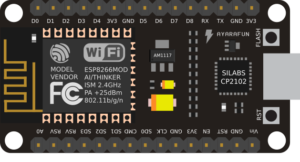 The ESP8266 NodeMCU is a small but extremely powerful development board based on the popular ESP8266 chip from Espressif. Equipped with an integrated Wi-Fi module operating at 802.11 b/g/n, it allows easy connection to existing wireless networks and communication with other devices over the Internet.
At the heart of the board is a 32-bit Tensilica L106 processor at 80-160 MHz and 64 KiB of instruction memory and 96 KiB of data memory. The NodeMCU has a built-in USB-UART converter (CP2102), so it can be easily connected to a computer and programmed using the Arduino IDE or other environment.
A key advantage is the existence of as many as 17 GPIO (General-Purpose Input/Output) pins, which can be freely used as digital I/O or assigned other functions, such as I2C, SPI, UART, etc. This allows communication and control of all kinds of sensors, displays and executive devices.
Despite its compact size and low price, the ESP8266 NodeMCU has great potential in DIY and Internet of Things projects thanks to its strong capabilities, low cost and excellent community support.
What is ESPHome?

ESPHome is a powerful, open source development environment designed specifically for devices based on the popular ESP8266 and ESP32 microcontrollers. Its main goal is to facilitate the creation of smart Internet of Things (IoT) devices, which can then be fully integrated and controlled through the Home Assistant platform.
Configuration of devices in ESPHome is done through friendly files in YAML format, which allow defining the operation of various components, sensors, displays or actuators. This makes programming intuitive and accessible even to those without in-depth coding knowledge.
In addition to native integration with Home Assistant, ESPHome also supports a wide range of off-the-shelf modules and libraries, allowing it to support many popular other components.
Preparation
Before diving into system adaptation using ESP and ESPHome, it’s a good idea to prepare properly. Below you will find key steps to get your project started.
Make sure you have all the necessary materials:
- ESP8266 NodeMCU board (or ESP32, if you opt for a newer model),
- It is worth verifying before purchasing an ESP board that Wi-Fi coverage reaches our installation site. We may need to purchase a board with the ability to connect an external antenna.
- PZEM004T v3 – single-phase electricity meter (Link to shop),
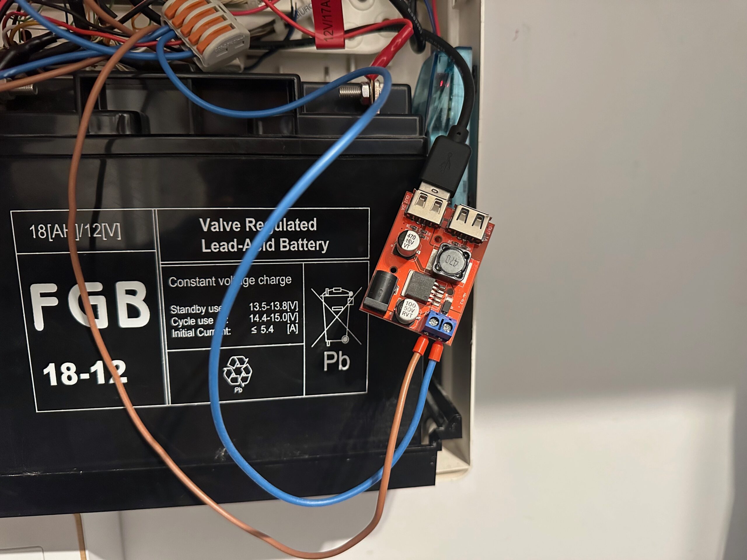
- Power source for the ESP board (5V DC),
- Wire connectors,
- (Optional) DIN box in which to hide the ESP board with the converter module,
- Connection wires for all components.
Installing ESPHome in Home Assistant
Install ESPHome in your Home Assistant environment to easily configure and manage the ESP8266. Use the ESPHome documentation and follow the instructions.
Preparation of workspace
Organize a workspace where you will assemble the system. Make sure you have access to tools and are comfortable working on the project.
Health and safety of working with electric voltage
 Electrical safety is key when working with electricity. Here are some important recommendations:
- Power Off: Before any work on the circuit, turn off the power supply to avoid electric shock.
- Appropriate Tools: Use tools that are insulated and designed for electrical work – they should meet appropriate safety standards.
- Experience: Electrical installation work requires experience. If you are unsure of your skills, it is advisable to enlist the help of an experienced person.
- Eye and Hand Protection: Wearing eye and hand protection is recommended, especially when soldering and handling connections.
- Check the Power Supply: Make sure you know where the main power supply is and that it is off before taking any action.
- Knowledge of the Electrical System: Always verify that you know how an electrical system works. Do not take action blindly.
Step 1 – VLAN IoT
As a security practice, I recommend setting up a separate network for IoT devices, separate from the main home network. For this purpose, it is worth using the VLAN (Virtual Local Area Network) function, which allows physical separation of devices, such as those based on ESPHome, from other devices in the home infrastructure.
Benefits

Creating a dedicated network for IoT devices offers several advantages:
- Security: Separating IoT devices from the main network haelps minimize the potential risk of attacks. If an IoT device is possibly compromised, access to the main home network is difficult.
- Controlling Communications: Creating a separate network allows for more precise control over who communicates with IoT devices and how. You can define communication rules that only allow specific devices (for example, a server or virtual machine from Home Assistant) to interact with IoT devices.
- Network Traffic Optimization: Separating IoT device traffic from main network traffic can help optimize network performance.
Implementation
To implement such separation, it is worth consulting the documentation and settings of the router. In the case of Home Assistant, using the appropriate firewall rules on the router, you can customize access to IoT devices. This approach introduces a layer of additional security to our smart home infrastructure.
Step 2 – Install and configure firmware to work with Home Assistant
Once you run the ESPHome add-on on the Home Assistant server, you can proceed to add your first ESPHome-based device.
Connecting to a computer
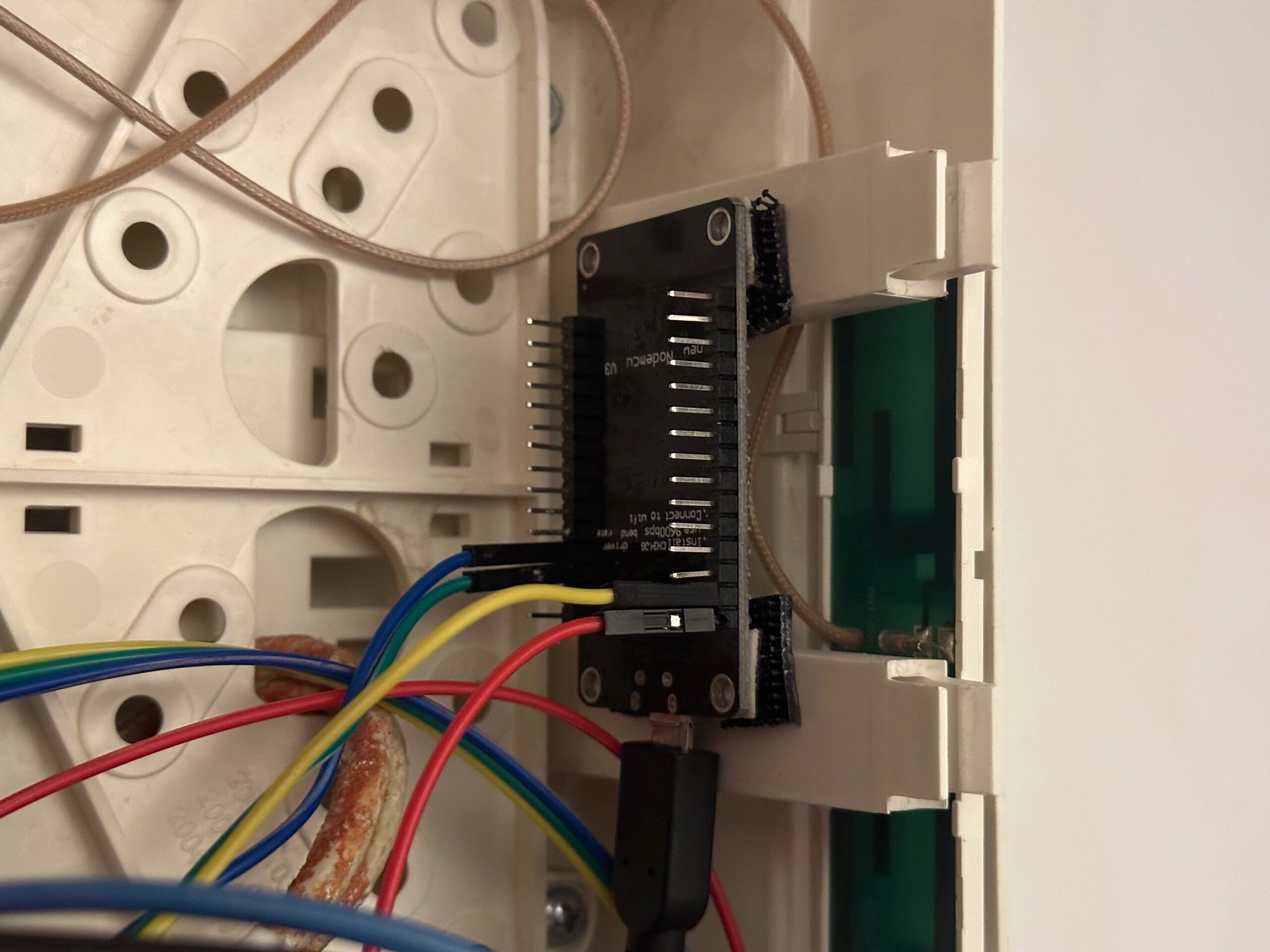
- Connect the board using a USB cable to your computer. It is important to use a USB cable with data transmission, as many cheap cables only provide power.
- To be sure of correct operation, I recommend using Chrome or Edge browser (there is a transfer of data transmission through the COM port to the browser using WebSerial).
Home Assistant
- After completing these steps, log in to Home Assistant,
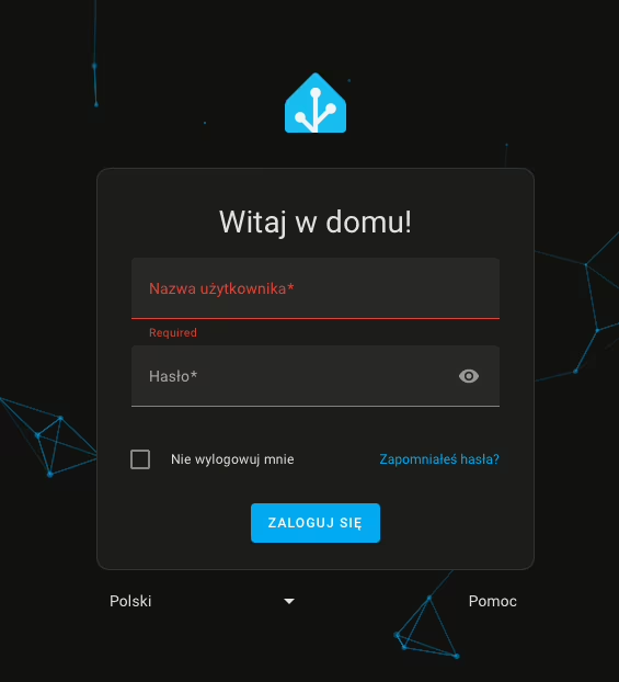
- From the side panel, go to the ESPHome tab,
- Then click New Device,
After selecting the option to add a new device, we may encounter a browser incompatibility message, especially for browsers that do not support WebSerial. Alternatively, we may also encounter a message indicating that there is no secure connection (HTTPS) to the dashboard. In this situation, we can click Continue to continue the process of adding the device.
- In the next window, we enter a name for our device (it can be a name or alias we created) and the details of our Wi-Fi network.
- Wi-Fi network entry is only necessary when adding a device for the first time. Subsequent ESPHome-based additions will not require this step.
- Then, for ESPHome to install the firmware on the ESP8266 board, click Connect.
- After a while, the browser will display a window for selecting a device for serial port communication. Find your device, whose name should include CP210x UART, and click Connect.
- Then wait until the firmware is installed on the board.
Completion of the process
After a successful installation, you should receive a message confirming the completion of the process. Your device will also appear on the dashboard with the description ONLINE. This means that the board has been correctly configured and is ready to proceed.
Step 3 – Mount the module
Connecting the PZEM004T v3 energy meter to the electrical system requires accuracy and following proper safety procedures.
Types of modules
When installing the module, it is worth noting the two types of models available: supporting currents up to 10A and up to 100A. The difference between them lies mainly in the way the current transformer (CT) is connected.
10A version: The module contains a built-in current sensor that directly measures the current flowing through the circuit. This is simpler to install, but limited to circuits that do not exceed 10A.
100A version: This version uses an external current transformer (CT), which is more flexible for installation. This transformer must be mounted on the phase conductor, and has the advantage that it can be easily attached to the existing conductor without disconnecting the installation. It is ideal for monitoring larger circuits with currents up to 100A.
The installation method described will be based on the 100A version using a current transformer.
Preparation
- Location selection: The PZEM004T v3 module does not have a display, so you don’t need to install it in a location that is easily accessible for reading data. You can mount it in any safe location near the circuit you want to monitor. However, it is important that the mounting location is dry, well ventilated and complies with local electrical codes.
- Installation preparation: Turn off the power to the electrical circuit where you will be installing the meter. Always make sure you work in a de-energized condition to avoid the risk of electric shock. Check that the wires are dry and free from damage.
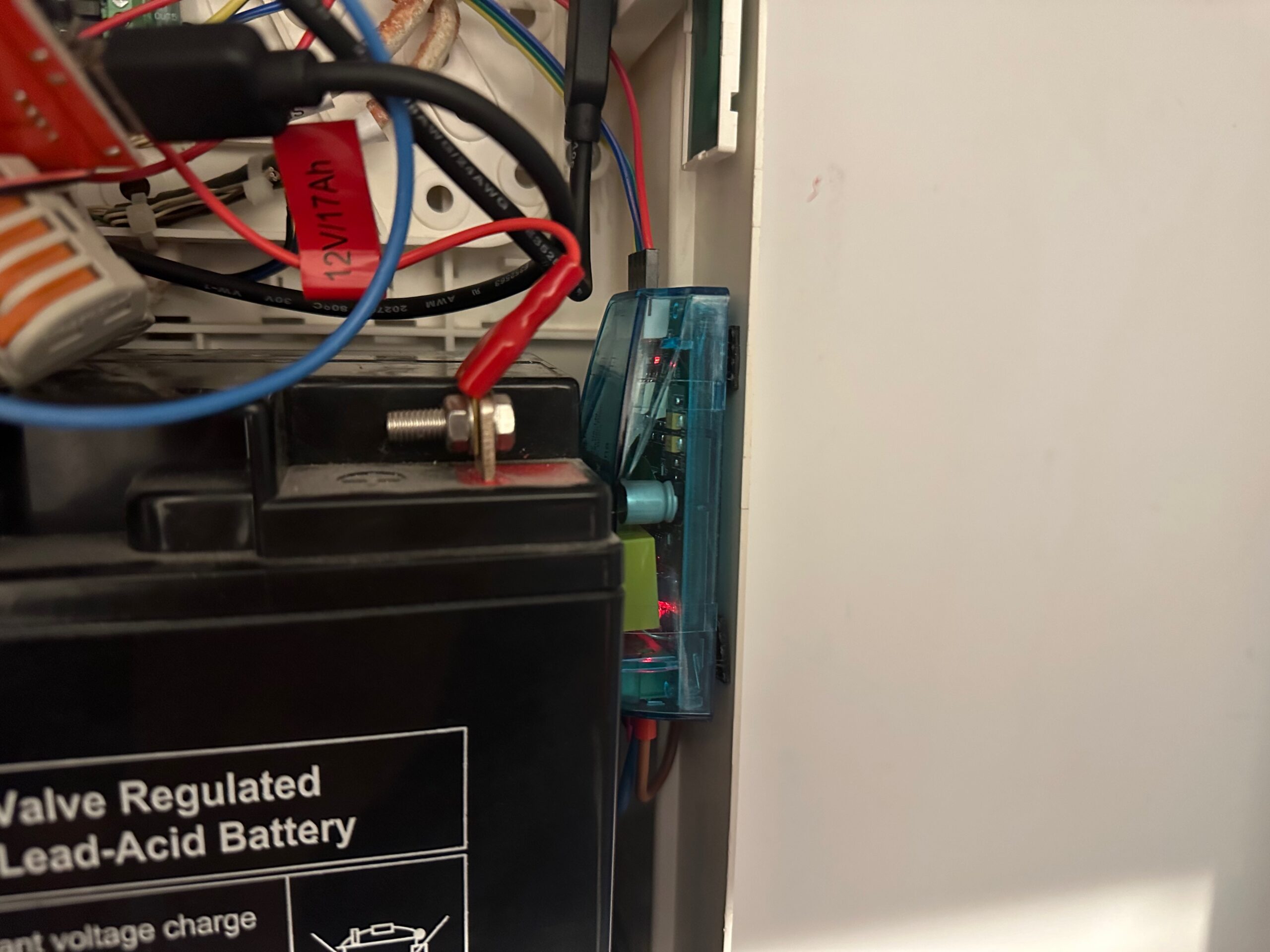
- Module installation: Mount the PZEM004T v3 in the desired location using the fasteners of your choice. Make sure the module is firmly attached to avoid accidental damage during use.
Actions
- Connecting electrical wires:
- Current transformer (CT): The current transformer (split-core) should be installed on the phase conductor (L) of the circuit you wish to monitor. Ensure that the arrow on the transformer housing points in the direction of the current flow, from the energy source to the load. This positioning is crucial for accurate readings. Unlike a standard conductor, the CT doesn’t carry the current directly through itself. Instead, it detects the magnetic field generated by the current flow, enabling it to measure the current without interrupting the circuit.
- Phase wire (L): The phase wire connected to the PZEM004T module doesn’t carry the full load of current; its primary role is to measure the voltage in the circuit. It should be connected to the designated terminal on the module, as indicated by the markings. Proper connection of the phase wire ensures that the meter can accurately monitor the voltage in the system.
- Neutral (N) wire: The neutral wire is used for voltage measurement in the system and must be connected to the appropriate terminal on the PZEM004T module. Unlike the phase wire, the neutral does not pass through the current transformer (CT), but its connection is essential for accurate voltage measurements and overall functionality of the monitoring system.
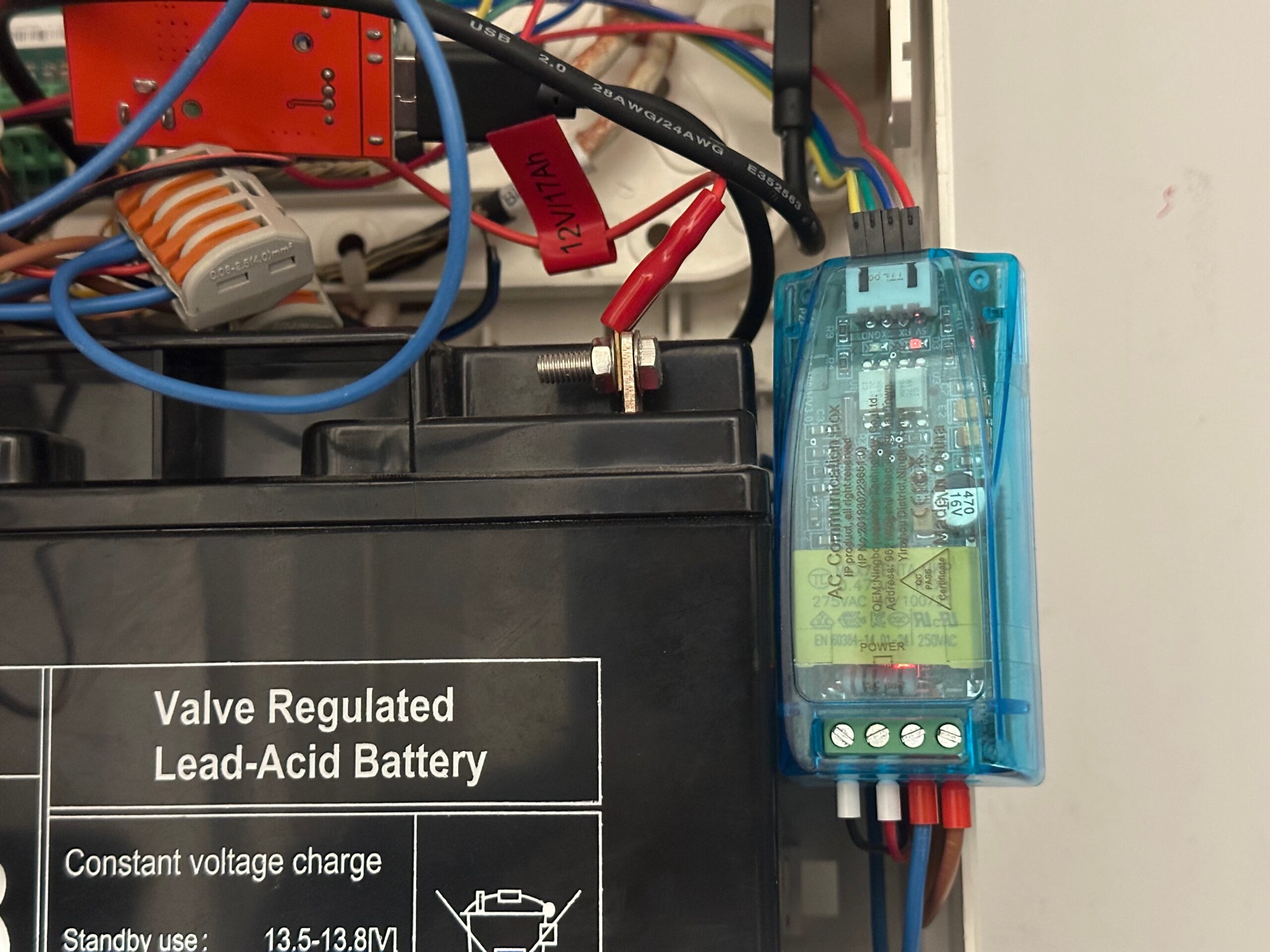
- Power on: Once the connection is complete, power up the circuit and verify that the module is working properly. PZEM004T v3 communicates via UART, so verification of proper operation will be through readings in ESPHome or Home Assistant.
Recommendations
- Checking connections: Make sure all wires are securely fastened and connections are well insulated. Loose connections can lead to incorrect readings or pose a safety hazard.
- Testing: Check that all parameters are correctly reported by the module in the monitoring system. You can run load tests to make sure the meter is accurately monitoring power consumption.
- Use of cable ferrules: Crimping ferrules should be applied to the ends of cable wires to prevent them from fraying during terminal installation. By using these sleeves, you ensure a more durable connection, improve electrical contact, and protect the wires from mechanical damage that can occur while tightening the terminals.
Discover the secrets of installing and configuring your own ADS-B antenna on a Raspberry Pi. Develop skills and track aircraft in real time.
How to install TVHeadend on a Synology with Docker Compose. A practical step-by-step guide for advanced users.

Configure Single Sign-On between Authentik and WordPress for secure and comfortable login. Learn about step-by-step configuration.
Installation and integration of the Eastron SDM120M energy meter with Home Assistant using ESPHome. A detailed step-by-step guide.

Welcome on my blog, where ‘Hello World’ is a symbolic start. Discover with me the fascinating world of coding and news from the world of technology.
Discover how to quickly install Portainer on Synology – simple step-by-step instructions. Manage your Docker containers today!
Comments (2)
Lyksays:
06/04/2025 at 21:42Nice and thank you!
A few comments in case you want to update the guide:
1. Power factor will shows as 1% when is should be 100% with the given config. It should use a filter in order to show the correct percentage.
power_factor:
name: “Power Factor”
id: “pzem_power_factor”
unit_of_measurement: “%”
accuracy_decimals: 1
filters:
– lambda: return x * 100.0;
2. Under sensor -> energy it would be nice to also add:
device_class: energy
state_class: total_increasing
This will help HA to show the device in the Energy Tab (one will need to add the device via the “Energy Configuration”)
3. PZEM signals seems to be 5V but the ESP32 and ESP82666 use 3.3V logic pins.
as a result, the TX of the PZEM needs to be lowered from 5V to 3.3V. Using a voltage divider with one 1kΩ resistor and one 2kΩ resistor will do the trick.
It seems to work even without that, but may not be as reliable or could cause damage to the ESP module.
Thank you!
Filip Chochółsays:
16/04/2025 at 12:251. In my configuration, I see no problem in converting the power factor. For example – now I have 16.3W active power, apparent 21.63 VA. The result is circa about 0.781 %
2. I had no problem adding the kWh taken to the Energy tab