Hello!
Are you tired of having to remember to take the remote control with you from your apartment every time you leave and enter the housing estate? Or would you like to provide remote access to your gate or barrier to other householders without paying additional charges?
In today’s post, I’ll show you step-by-step how to integrate and automate barrier control via Home Assistant using an inexpensive ESP8266 NodeMCU board and open source ESPHome software.
This solution will not only increase comfort and convenience, but will also make it possible to assign access to the family without the need for additional remote controls. We will achieve all this with the available tools and an actual case study performed on my apartment complex.
Ready? Here we go! 🚀
What is the ESP8266 NodeMCU?
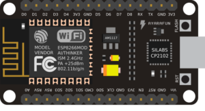 The ESP8266 NodeMCU is a small but extremely powerful development board based on the popular ESP8266 chip from Espressif. Equipped with an integrated Wi-Fi module operating at 802.11 b/g/n, it allows easy connection to existing wireless networks and communication with other devices over the Internet.
At the heart of the board is a 32-bit Tensilica L106 processor at 80-160 MHz and 64 KiB of instruction memory and 96 KiB of data memory. The NodeMCU has a built-in USB-UART converter (CP2102), so it can be easily connected to a computer and programmed using the Arduino IDE or other environment.
A key advantage is the existence of as many as 17 GPIO (General-Purpose Input/Output) pins, which can be freely used as digital I/O or assigned other functions, such as I2C, SPI, UART, etc. This allows communication and control of all kinds of sensors, displays and executive devices.
Despite its compact size and low price, the ESP8266 NodeMCU has great potential in DIY and Internet of Things projects thanks to its strong capabilities, low cost and excellent community support.
What is ESPHome?
![]()
ESPHome is a powerful, open source development environment designed specifically for devices based on the popular ESP8266 and ESP32 microcontrollers. Its main goal is to facilitate the creation of smart Internet of Things (IoT) devices, which can then be fully integrated and controlled through the Home Assistant platform.
Configuration of devices in ESPHome is done through friendly files in YAML format, which allow defining the operation of various components, sensors, displays or actuators. This makes programming intuitive and accessible even to those without in-depth coding knowledge.
In addition to native integration with Home Assistant, ESPHome also supports a wide range of off-the-shelf modules and libraries, allowing it to support many popular other components.
Preparation
Before we dive into adapting the remote control to our system using the ESP8266 and ESPHome, it’s a good idea to prepare properly. Below you will find the key steps to get your project started:
Required equipment and components
Make sure you have all the necessary materials:
- ESP8266 NodeMCU board (or ESP32, if you opt for a newer model),
- It is worth verifying before purchasing an ESP board that Wi-Fi coverage reaches our installation site. We may need to purchase a board with the ability to connect an external antenna.
- Relay module 1 channel – contacts 10A/250VAC – coil 5V,
- Remote control for our barrier / garage door,
- Power source for the ESP8266 board (5V DC),
- Wire connectors,
- A box in which to hide the board along with the relay module (weatherproof),
- Box, in which we hide the remote control that is within the range of our barrier / garage door (weatherproof),
- Connection wires for all components.
Installing ESPHome in Home Assistant
Install ESPHome in your Home Assistant environment to easily configure and manage the ESP8266. Use the ESPHome documentation and follow the instructions.
Preparation of workspace
Organize a workspace where you will assemble the system. Make sure you have access to tools and are comfortable working on the project.
Step 1 – VLAN IoT
As a security practice, I recommend setting up a separate network for IoT devices, separate from the main home network. For this purpose, it is worth using the VLAN (Virtual Local Area Network) function, which allows physical separation of devices, such as those based on ESPHome, from other devices in the home infrastructure.
Benefits
Creating a dedicated network for IoT devices offers several advantages:
- Security: Separating IoT devices from the main network haelps minimize the potential risk of attacks. If an IoT device is possibly compromised, access to the main home network is difficult.
- Controlling Communications: Creating a separate network allows for more precise control over who communicates with IoT devices and how. You can define communication rules that only allow specific devices (for example, a server or virtual machine from Home Assistant) to interact with IoT devices.
- Network Traffic Optimization: Separating IoT device traffic from main network traffic can help optimize network performance.
Implementation
To implement such separation, it is worth consulting the documentation and settings of the router. In the case of Home Assistant, using the appropriate firewall rules on the router, you can customize access to IoT devices. This approach introduces a layer of additional security to our smart home infrastructure.
Step 2 – Install and configure firmware to work with Home Assistant
Once the ESPHome add-on is running on the Home Assistant server, it’s time to move on to adding the first ESPHome-based device.
Connecting to a computer
- Connect the board using a USB cable to your computer. It is important to use a USB cable with data transmission, as many cheap cables only provide power.
- To be sure of correct operation, I recommend using Chrome or Edge browser (there is a transfer of data transmission through the COM port to the browser using WebSerial).
Home Assistant
- After completing these steps, log in to Home Assistant,
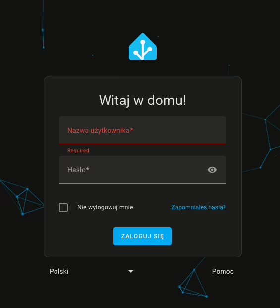
- From the side panel, go to the ESPHome tab,
- Then click New Device,

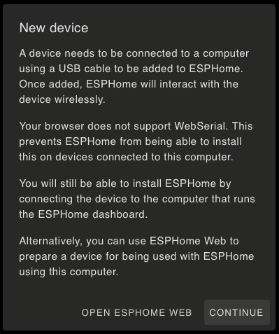
After selecting the option to add a new device, we may encounter a browser incompatibility message, especially for browsers that do not support WebSerial. Alternatively, we may also encounter a message indicating that there is no secure connection (HTTPS) to the dashboard. In this situation, we can click Continue to continue the process of adding the device.
- In the next window, we enter a name for our device (it can be a name or alias we created) and the details of our Wi-Fi network.
- Wi-Fi network entry is only necessary when adding a device for the first time. Subsequent ESPHome-based additions will not require this step.
- Then, for ESPHome to install the firmware on the ESP8266 board, click Connect.
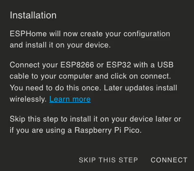
- After a while, the browser will display a window for selecting a device for serial port communication. Find your device, whose name should include CP210x UART, and click Connect.
- Then wait until the firmware is installed on the board.
Completion of the process
After a successful installation, you should receive a message confirming the completion of the process. Your device will also appear on the dashboard with the description ONLINE. This means that the board has been correctly configured and is ready to proceed.
Step 3 – Upload the code to control the barrier in ESPHome
# boom-barrier control v 1.0 #
esphome:
  name: esp01-boom-barrier
  friendly_name: esp01-boom-barrier
  on_boot:
    then:
    - cover.close: gate

esp8266:
  board: esp01_1m

# Enable logging
logger:

web_server:
  port: 80

# Enable Home Assistant API
api:
  encryption:
    key: "HERE WILL BE THE GENERATED CODE BY ESPHOME"

ota:
  password: "HERE WILL APPEAR THE PASSWORD GENERATED BY ESPHOME"

wifi:
  ssid: !secret wifi_ssid
  password: !secret wifi_password

  # Enable fallback hotspot (captive portal) in case wifi connection fails
  ap:
    ssid: "Esp01-Boom-Barrier Fallback Hotspot"
    password: "1234567890"

captive_portal:

# FROM HERE YOU CAN COPY THE CONTENT #
# I've included all the code as an example of what it should look like #

switch:
  - platform: gpio
    pin: GPIO14
    name: "Remote - Button 01"
    icon: "mdi:boom-gate"
    id: gate_relay
    inverted: true
    internal: true

cover:
  - platform: template
    name: "Boom barrier"
    id: gate
    optimistic: true
    open_action:
      - switch.turn_on: gate_relay
      - delay: 1000ms
      - switch.turn_off: gate_relay
      - delay: 2s
      - lambda: |-
          id(gate).publish_state(COVER_OPEN);
      - delay: 10s
      - lambda: |-
          auto call = id(gate).make_call();
          call.set_command_close();
          call.perform();
    close_action:
      - lambda: |-
          ESP_LOGD("custom", "Executing close action lambda");
id(gate).publish_state(COVER_CLOSED);- We are waiting for the software to be compiled and uploaded to the board. If the installation process is successful, the log preview will show you a summary of your board’s configuration.
Step 4 – Connect all components to the board
Remember to perform these activities with the highest standards of electrical safety. Make sure all connections are properly secured.
Adjusting the remote control
- Disassemble the remote control and bring out the wires to short the micro switch:
- Most gate and barrier remotes have micro switches that act as buttons. When pressed, a given micro switch is shorted, passing the signal to open the gate.
- Locate on the remote control board the correct micro-switch responsible for the barrier/gate opening signal.
- Carefully solder two wires to the contacts of this micro-switch in such a way that you can fake short-circuit them in a way that mimics pressing a button.
Installation
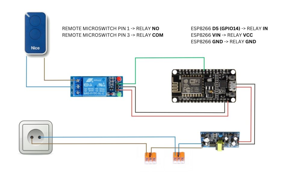
- Connect the quick-connect electrical plugs or use a 5V mains charger:
- Connect the phase and neutral wires to the quick-connect electrical connectors. These connectors will serve as a power distribution point – you may find it useful in the future. Note: Do not connect the connectors to the voltage yet.
- Connect the power supply to the inverter:
- From the quick-connectors, run power to the inverter, which converts the voltage from 230V AC to 5V DC. This step is essential because it provides the proper power supply for the ESP8266 board.
- Powering the ESP8266 board:
- From the ESP8266 board, lead the 5V DC power wires from the inverter. You can connect the board’s power supply to the microUSB connector.
- Also lead the communication wire from the ESP8266 to the relay, which will be used to control the relay shorting.
- Connecting the relay
- Connect one of the cables from the remote control to the terminal marked NO (Normally Open) on the relay module.
- Connect the second cable to the terminal marked COM (Common) on the relay module.
- After such a connection, when the relay is activated (switched on), the NO and COM contacts will be short-circuited – this short-circuit will simulate the situation of short-circuiting the micro switch, as if you physically pressed the button on the remote control. As a result, this will send a signal to open the barrier/gate, exactly the same as when using the original remote control.
Final verification
- Make sure all connections are properly secured:
- Check that the board contacts do not touch the metal (if any) parts of the hermetic case or other wires that could damage your electronics.
- Connect the installation to the power supply:
- Wait for the ESP8266 board to connect to your Wi-Fi network.
Now we will proceed to add the new device to the integration section of Home Assistant.
Step 5 – Reverse proxy on Synology using Nginx Proxy Manager
Do you use Synology and want to improve access to your Home Assistant server? Here’s a quick step-by-step guide on how to set up a login using a domain name and subdomain, such as ha.xyz.com, instead of entering an IP address. You can achieve all this with Docker Compose in the Portainer.
👉 Check it out now and get your environment ready for more improvements!
Thus, by using a domain name instead of an IP address, you simplify the process of logging into your Home Assistant server on Synology.
Step 6 – Adding a device to Home Assistant
- In the Home Assistant notification section, you should see that our home automation server has detected a new device,
- Go to Settings, then to Integrations and Devices.
- The new device will bear a blue border. We approve the new device for integration.
- Set the area where the device will be located. In our case, it will be the Loggia.
- Congratulations! You have reached this stage, which means that you have successively gone through the configuration process. To check the operation of the new device, you can directly go to it and control the opening of the barrier / garage door from the Home Assistant.🚀

Apple HomeKit > CarPlay
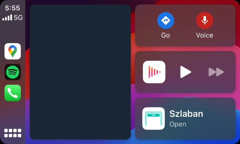
If you already have Apple HomeKit integration set up in Home Assistant, allowing you to control various devices via the Home app on iOS, you can easily add an entity representing the gate/barrier to it as well.
Once you have successfully configured and exposed this entity to Apple HomeKit, you will be able to see the button to open the gate directly on the screen of the car’s multimedia system, which supports the Apple CarPlay standard.
This will give you the convenient ability to remotely open the passage to the estate already during your commute, without having to reach for your smartphone or remote control. A single click on the multimedia system screen in the car is all it takes to activate the gate.
This functionality is extremely useful because the car system detects your location and automatically displays useful actions to perform near your location. Thus, the possibility of opening the entrance gate will be displayed at the right moment as soon as you are within range of your estate.
Additional materials and information
For further exploration and more information, I recommend checking out the links below. They are valuable sources that were used in the development of this guide.
- Getting Started with ESPHome and Home Assistant: https://esphome.io/guides/getting_started_hassio#installing-esphome-dashboard
Read also
- TVHeadend: Installing and configuring SAT>IP decoder / Telestar Digibit Twin: Discover in today’s blog post the step-by-step configuration of SAT>IP with TVHeadend in Docker Compose.
- How to configure Leox GPON ONT insert on Mikrotik router / Step-by-step guide on how to configure Leox LXT-010S-H GPON ONT insert on Mikrotik RB5009 router, instead of ONT module from Orange.
- UniFi Network Application: Connecting an Access Point from another network / Discover how to connect a device from Ubiquiti UniFi from another network to Network Application – using Mikrotik’s IPSec tunnel as an example.
- UniFi Controller in Docker: Migrating to UniFi Network Application / UniFi Controller: Discover step-by-step how to successfully migrate to Network Application using Docker Compose.
- Home Assistant: Install mirror lighting on ESPHome / Set up simple mirror lighting with ESPHome in Home Assistant. Discover simple integration and control light with ease.
- ADS-B: Receiver Installation and Configuration on Raspberry Pi / Discover the secrets of installing and configuring your own ADS-B antenna on Raspberry Pi. Develop skills and track aircraft in real time.
- Traccar: A guide to installing on Synology with Docker / Step-by-step guide: Installing Traccar on Synology using Docker. Effective vehicle tracking on your own server.
Leave a Reply